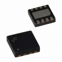
FAN5608DMPX Fairchild Semiconductor, FAN5608DMPX Datasheet - Page 6

FAN5608DMPX
Manufacturer Part Number
FAN5608DMPX
Description
IC LED DRIVER WHITE BCKLGT 8-MLP
Manufacturer
Fairchild Semiconductor
Type
Backlight, White LED (Serial Interface)r
Datasheet
1.FAN5608DHMPX.pdf
(15 pages)
Specifications of FAN5608DMPX
Topology
PWM, Step-Up (Boost)
Number Of Outputs
2
Internal Driver
Yes
Type - Primary
Backlight
Type - Secondary
White LED
Frequency
500kHz
Voltage - Supply
2.7 V ~ 5.5 V
Voltage - Output
24V
Mounting Type
Surface Mount
Package / Case
8-MLP
Operating Temperature
-40°C ~ 85°C
Current - Output / Channel
20mA
Internal Switch(s)
Yes
Efficiency
85%
Number Of Segments
12
Operating Supply Voltage
2.7 V to 5.5 V
Maximum Operating Temperature
+ 85 C
Mounting Style
SMD/SMT
Minimum Operating Temperature
- 40 C
Lead Free Status / RoHS Status
Lead free / RoHS Compliant
Other names
FAN5608DMPXTR
FAN5608DMPX_NL
FAN5608DMPX_NLTR
FAN5608DMPX_NLTR
FAN5608DMPX_NL
FAN5608DMPX_NLTR
FAN5608DMPX_NLTR
REV. 0.8.3 5/29/03
1. A is PWM Controlled, B is Low. I
Note:
3. Proportionally select the duty cycle to achieve a typical LED current between 1mA to 4mA.
Preliminary Data Sheet
Digital Control
The FAN5608’s digital decoder allows selection of the fol-
lowing modes of operation: OFF, 5mA, 10mA, 20mA per
branch.
Analog Control with PWM
Inputs A1 and A2 are used to control the LED currents.
Inputs B1 and B2 should be connected to GND (logic level
"0"). An external resistor (R) is connected from A1 and/or
A2 to a stable voltage source (V
LED current, I
follows:
Where
Pulse-Width-Modulation (PWM) Control
A variable duty cycle( ) can modulate any DAC input. Care
should be taken to not use a too low frequency, otherwise a
flickering effect may occur. The minimum range is 100Hz to
1KHz. For a maximum range of LED current, both A and B
inputs can be modulated at the same time.
PWM Control
I
LED
A
B
V
Ref
I
OFF
LED
=
0
0
LED
A Input (PWM)
B Input (0)
I LED
1.22V
=
. The formula used to calculate I
5mA
V
---------------------------------------- -
1
0
External
0mA
R
10mA
–
0
1
EXTERNAL
V
Ref
Duty Cycle
20mA
LED
1KHz
30%
1
1
I
LED
1000
) to control the
(Average) = x 5mA, where
(Average) = 0.3 x 5mA = 1.5mA
LED
is as
No Load Protection
A built-in over voltage protection circuit prevents the device
from being damaged when it is powered up with no load.
This circuit reduces the boost converter duty cycle, to a min-
imum thus limiting the output voltage to a safe value when
no load condition is detected. If one of the two enable
branches is accidentally disconnected, the converter contin-
ues the operation, however, the current in the remaining
branch is no longer regulated and the actual branch current
will be determined by the input voltage, the inductor value
and the switching frequency.
However, the FAN5608 can be damaged when a full load
(more than six LEDs, driven by 20mA) is suddenly discon-
nected from V
unlikely event, an external 20V Zener diode can be con-
nected between V
Shutdown Mode
Each branch can be independently disabled by applying
LOW logic level voltage to the A and B inputs. When both
branches are disabled, the FAN5608 enters Shutdown mode
and the supply current is reduced to less than 1 A.
is Duty Cycle. (Note 3)
OUT
Duty Cycle
OUT
I
LED
1KHz
70%
. To protect the FAN5608 against this
(Average) = 0.7 x 5mA = 3.5mA
and GND.
OFF
FAN5608
6


