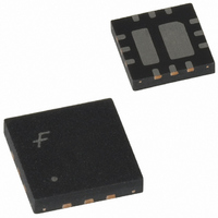
FAN5608HMPX Fairchild Semiconductor, FAN5608HMPX Datasheet - Page 5

FAN5608HMPX
Manufacturer Part Number
FAN5608HMPX
Description
IC LED DRIVR WHITE BCKLGT 12-MLP
Manufacturer
Fairchild Semiconductor
Type
Backlight, White LED (Serial Interface)r
Datasheet
1.FAN5608DHMPX.pdf
(15 pages)
Specifications of FAN5608HMPX
Topology
PWM, Step-Up (Boost)
Number Of Outputs
2
Internal Driver
Yes
Type - Primary
Backlight
Type - Secondary
White LED
Frequency
500kHz
Voltage - Supply
2.7 V ~ 5.5 V
Voltage - Output
24V
Mounting Type
Surface Mount
Package / Case
12-MLP
Operating Temperature
-40°C ~ 85°C
Current - Output / Channel
20mA
Internal Switch(s)
Yes
Efficiency
85%
Number Of Segments
12
Operating Supply Voltage
2.7 V to 5.5 V
Maximum Supply Current
0.1 mA
Maximum Operating Temperature
+ 85 C
Mounting Style
SMD/SMT
Minimum Operating Temperature
- 40 C
Lead Free Status / RoHS Status
Lead free / RoHS Compliant
Other names
FAN5608HMPXTR
FAN5608HMPX_NL
FAN5608HMPX_NLTR
FAN5608HMPX_NLTR
FAN5608HMPX_NL
FAN5608HMPX_NLTR
FAN5608HMPX_NLTR
Preliminary Data Sheet
REV. 0.8.3 5/29/03
Block Diagram
Circuit Description
When the input voltage is connected to V
turned on, the bandgap reference acquires its nominal volt-
age and the soft-start cycle begins. Once "power good" is
achieved (0.5mA in the diodes), the soft-start cycle stops and
the boost voltage increases to generate the desired current
selected by the input control pins. If the second channel is
not selected, its output will go high to about V
diodes are turned off.
The FAN5608 DC/DC converter automatically adjusts its
internal duty cycle to achieve high efficiency. It provides
tightly regulated output currents for the LEDs. An internal
circuit determines which LED string requires the highest
voltage in order to sustain the pre-set current levels, and
adjusts the boost regulator accordingly.
B2
A2
B1
A1
V
IN
Note: In the 8-pin version (analog version only), pins B1 and B2 are omitted.
DAC1
DAC2
GND
BG
IN
pin, the system is
OSC
IN
START-UP
, and the
POWER GOOD
REF
REF CH1
REF CH2
DBB
To maintain the regulated current at the selected value, the
difference in the number of LEDs between branches should
not exceed two. If only one branch is used, another branch
should be disabled, connecting the corresponding DAC
inputs to low. If the output external capacitor is shorted, the
Schottky diode can be damaged, therefore such condition
should be avoided.
LED Brightness Control
The control inputs are A1, B1 for CH1 and A2, B2 for CH2.
B1 and B2 are digital inputs, thus they require LOW (GND)
and HIGH (V
A2 are connected to an external stable voltage source via an
external resistor, and B1 and B2 inputs are connected to
ground. The current flowing through the resistor is scaled by
a factor of approximately 1000.
COIL DRIVER
CC
) control signals. In analog mode, A1 and
LINEAR REGULATOR
LINEAR REGULATOR
W_OR
V
CH2
CH1
IND
OUT
FAN5608
5


