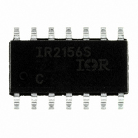
IR2156STRPBF International Rectifier, IR2156STRPBF Datasheet

IR2156STRPBF
Specifications of IR2156STRPBF
IR2156STRPBF
IR2156STRPBFTR
Available stocks
Related parts for IR2156STRPBF
IR2156STRPBF Summary of contents
Page 1
Features Description CFL Application Diagram R D BOOT VCC VDC VCC2 VCC1 C BOOT RPH ...
Page 2
S ) & (PbF) IR2156 Absolute Maximum Ratings Symbol Definition Min. ° Max. Units ...
Page 3
Recommended Operating Conditions Symbol Definition Electrical Characteristics Symbol Definition Supply Characteristics Floating Supply Characteristics IR2156 Min. Min. Typ. Max. Units Test Conditions ( S ) & (PbF) Max. Units — ...
Page 4
S ) & (PbF) IR2156 Electrical Characteristics Symbol Definition Oscillator, Ballast Control, I/O Characteristics Preheat Characteristics RPH Characteristics RT Characteristics Protection Characteristics Gate Driver Output Characteristics Min. Typ. Max. Units Test Conditions ...
Page 5
Block Diagram Vcc 40K R Comp RDT TH 2. RPH R ICPH CPH 5.1V 5.1V RVDC VDC 10K SD 5.1V Comp 2 COM Lead Assignments & Definitions Driver Logic ...
Page 6
S ) & (PbF) IR2156 State Diagram CS > 1.3V (Lamp Removal > 5.1V or VCC < 9.5V (UV-) (Power Turned Off) FAULT Mode Fault Latch Set 1 / -Bridge Off 2 I 180 A QCC CPH ...
Page 7
VCC 15.6V UVLO+ UVLO- VDC VCC 7.5V CPH FREQ 1.3V UVLO PH RT RPH Timing Diagrams f run Over-Current Threshold RUN RT RPH & ...
Page 8
S ) & (PbF) IR2156 Timing Diagrams VCC 15.6V UVLO+ UVLO- VDC VCC 7.5V CPH FREQ 1.3V UVLO PH RT RPH RPH CSTH CS ...
Page 9
120 RPH=15K 110 100 90 80 RPH=30K (V) CPH ...
Page 10
S ) & (PbF) IR2156 (V) CPH 2 1 (V) CC 1000000 100000 10000 1000 ...
Page 11
Temperature ° - Temperature °C 5 4.5 4 3.5 3 2.5 2 -25 0 100 125 ...
Page 12
S ) & (PbF) IR2156 6 5.75 5.5 5.25 5 4.75 4.5 4. Temperature ° 125 ( ...
Page 13
V (V) CC 58.5 58 57.5 57 56.5 56 55 (V) CC IR2156 ...
Page 14
S ) & (PbF) IR2156 3.5 - 2.5 125 2 1 (V) CC 2.25 2.2 2.15 2.1 2.05 2 1.95 1.9 1.85 1 (V) CC ...
Page 15
C 100 - (V) CC 120 125 C 100 - ...
Page 16
S ) & (PbF) IR2156 Functional Description Under-voltage Lock-Out Mode (UVLO) V (+) BUS R D SUPPLY BOOT BOOT VCC IR2156 11 VCC COM (-) ...
Page 17
V (+) BUS RT OSC RPH Half- 5 Bridge R PH Driver 4uA CPH 7 C CPH IR2156 V (-) BUS Half Bridge VS Output 12 I LOAD Ignition ...
Page 18
S ) & (PbF) IR2156 Run Mode (RUN) DC Bus Under-voltage Reset Fault Mode (FAULT) ...
Page 19
Design Equations Step 1: Program Dead-time t C 2000 2000 Step 2: Program Run Frequency 1 f RUN 2000 ) 3333 T . ...
Page 20
S ) & (PbF) IR2156 . IGN IGN Design Example: 42W-QUAD BIAX CFL Step 1: Program Dead-time 400 pF T ...
Page 21
IGN 625 Ohms Results Parameter Description Waveforms . 0 61 Ohms Value ( S ) & (PbF) IR2156 ...
Page 22
S ) & (PbF) IR2156 Case outline 14-Lead PDIP 14-Lead SOIC (narrow body) ...
Page 23
Bill Of Materials ( S ) & (PbF) IR2156 ...
Page 24
S ) & (PbF) IR2156 LEADFREE PART MARKING INFORMATION Part number Date code Pin 1 Identifier ? MARKING CODE P Lead Free Released Non-Lead Free Released Basic Part (Non-Lead Free) 14-Lead PDIP IR2156 order IR2156 14-Lead SOIC IR2156S order ...


