FAN7392MX Fairchild Semiconductor, FAN7392MX Datasheet
FAN7392MX
Specifications of FAN7392MX
Available stocks


Related parts for FAN7392MX


FAN7392MX Summary of contents
Page 1
... Operating Part Number Temperature Range FAN7392N FAN7392M -40°C to +125°C FAN7392MX For Fairchild’s definition of Eco Status, please visit: http://www.fairchildsemi.com/company/green/rohs_green.html. © 2009 Fairchild Semiconductor Corporation FAN7392 Rev. 1.0.3 Description The FAN7392 is a monolithic high- and low-side gate drive IC, that can drive high-speed MOSFETs and IGBTs that operate up to +600V ...
Page 2
... Typical Application Diagrams 15V HIN Controller SD LIN Figure 1. Typical Application Circuit (Referenced 14-DIP) 15V HIN Controller SD LIN Figure 2. Typical Application Circuit (Referenced 16-SOP) © 2009 Fairchild Semiconductor Corporation FAN7392 Rev. 1.0 BOOT HIN BOOT BOOT V LIN COM BOOT HIN BOOT SD NC ...
Page 3
... SCHMITT TRIGGER INPUT LIN 14 CYCLE-By-CYCLE SD 13 EDGE TRIGGERED SHUTDOWN Pin 4, 5, 9,10 and 16 are no connection Figure 4. Functional Block Diagram (Referenced 16-SOP) © 2009 Fairchild Semiconductor Corporation FAN7392 Rev. 1.0.3 NOISE CANCELLER HS(ON/OFF) UVLO VSS/COM LS(ON/OFF) LEVEL SHIFT NOISE CANCELLER HS(ON/OFF) UVLO ...
Page 4
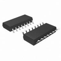
... Pin Configuration LO 1 COM Pin Definitions 14-Pin 16-Pin 4,8, 10, 16 © 2009 Fairchild Semiconductor Corporation FAN7392 Rev. 1.0 COM LIN HIN (a) 14-DIP (b) 16-SOP (Wide Body) Figure 5. Pin Configurations (Top View) Name LO Low-Side Driver Output COM Low-Side Return V Low-Side Supply Voltage CC V High-Voltage Floating Supply Return ...
Page 5
... Low-Side Output Voltage LO V Logic Supply Voltage DD V Logic Supply Offset Voltage SS V Logic Input Voltage IN T Operating Ambient Temperature A © 2009 Fairchild Semiconductor Corporation FAN7392 Rev. 1.0.3 =25°C unless otherwise specified. A Characteristics 14-PDIP ( 16-SOP 14-PDIP 16-SOP ) under any circumstances. D Parameter 5 Min ...
Page 6
... Allowable Negative Signal Propagation to HO © 2009 Fairchild Semiconductor Corporation FAN7392 Rev. 1.0.3 =COM=0V and T =25°C, unless otherwise specified. The and are applicable to the respective input leads: HIN, LIN, and SD. The V and COM and are applicable to the respective output leads: HO and LO. ...
Page 7
... Shutdown propagation Delay Time sd t Turn-On Rise Time r t Turn-Off Fall Time f MT Delay Matching, HO & LO Turn-On/Off Note: 4. These parameters guaranteed by design. © 2009 Fairchild Semiconductor Corporation FAN7392 Rev. 1.0.3 =COM=0V, C =1000pF, T =25°C, unless otherwise specified. LOAD A Conditions V = =0V S ...
Page 8
... Figure 6. Turn-On Propagation Delay vs. Temperature -40 - Temperature [°C] Figure 8. Turn-On Rise Time vs. Temperature -40 - Temperature [°C] Figure 10. Turn-On Delay Matching vs. Temperature © 2009 Fairchild Semiconductor Corporation FAN7392 Rev. 1.0.3 200 180 160 140 120 100 60 80 100 120 -40 -20 Figure 7. Turn-Off Propagation Delay 100 120 -40 -20 ...
Page 9
... Temperature [°C] Figure 14. Quiescent V CC vs. Temperature 1000 800 600 400 200 0 -40 - Temperature [°C] Figure 16. Operating V CC vs. Temperature © 2009 Fairchild Semiconductor Corporation FAN7392 Rev. 1.0.3 (Continued 100 120 -40 Figure 13. Logic Input High Bias Current 120 100 100 120 -40 Supply Current Figure 15 ...
Page 10
... Temperature [°C] Figure 20. V UVLO+ vs. Temperature BS 1.5 1.0 0.5 0.0 -40 - Temperature [°C] Figure 22. High-Level Output Voltage vs. Temperature © 2009 Fairchild Semiconductor Corporation FAN7392 Rev. 1.0.3 (Continued) 9.5 9.0 8.5 8.0 7.5 - 100 120 Figure 19. V 9.5 9.0 8.5 8.0 7.5 ...
Page 11
... Figure 24. Logic High Input Voltage vs. Temperature - -10 -11 -12 -40 - Temperature [°C] Figure 26. Allowable Negative V vs. Temperature - -10 -12 -14 - Supply Voltage [V] Figure 28. Allowable Negative Vs Voltage for HIN Signal Propagation to High Side vs. Supply Voltage © 2009 Fairchild Semiconductor Corporation FAN7392 Rev. 1.0.3 (Continued 15V 100 120 - 100 120 0 2 Voltage Figure 27. Input Logic (HIN & ...
Page 12
... Switching Time Definitions HIN SD LIN Figure 29. Switching Time Test Circuit (Referenced 14-DIP) HIN LIN HIN LIN HO LO © 2009 Fairchild Semiconductor Corporation FAN7392 Rev. 1.0.3 15V 1nF HIN 15V V LIN 10μF COM 1nF Shutdown Figure 30. Input/Output Timing Diagram 50 90% 90% 10% Figure 31. Switching Time Waveform Definitions ...
Page 13
... Switching Time Definitions HIN LIN © 2009 Fairchild Semiconductor Corporation FAN7392 Rev. 1.0.3 (Continued) 50 90% Figure 32. Shutdown Waveform Definition 50 10% 10% MT Figure 33. Delay Matching Waveform Definitions 13 50% MT 90% 90 www.fairchildsemi.com ...
Page 14
... S GND Figure 35. V Waveforms During Q1 Turn-Off S © 2009 Fairchild Semiconductor Corporation FAN7392 Rev. 1.0.3 Figure 36 and Figure 37 show the commutation of the load current between high-side switch, Q1, and low-side freewheelling diode, D3, in same inverter leg. The para- sitic inductances in the inverter circuit from the die wire ...
Page 15
... To reduce the EM coupling and improve the power switch turn-on/off performance, the gate drive loops must be reduced as much as possible. © 2009 Fairchild Semiconductor Corporation FAN7392 Rev. 1.0.3 Placement of Components transient performance The recommended placement and selection of compo- ...
Page 16
... Package drawings are provided as a service to customers considering Fairchild components. Drawings may change in any manner without notice. Please note the revision and/or date on the drawing and contact a Fairchild Semiconductor representative to verify or obtain the most recent revision. Package specifications do not expand the terms of Fairchild’s worldwide terms and conditions, specifically the warranty therein, which covers Fairchild products. Always visit Fairchild Semiconductor’ ...
Page 17
... Package drawings are provided as a service to customers considering Fairchild components. Drawings may change in any manner without notice. Please note the revision and/or date on the drawing and contact a Fairchild Semiconductor representative to verify or obtain the most recent revision. Package specifications do not expand the terms of Fairchild’s worldwide terms and conditions, specifically the warranty therein, which covers Fairchild products. Always visit Fairchild Semiconductor’ ...
Page 18
... Fairchild Semiconductor Corporation FAN7392 Rev. 1.0.3 18 www.fairchildsemi.com ...