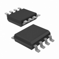
IR2301SPBF International Rectifier, IR2301SPBF Datasheet

IR2301SPBF
Specifications of IR2301SPBF
Related parts for IR2301SPBF
IR2301SPBF Summary of contents
Page 1
Features Description Typical Connection Data Sheet No. PD60201 Rev.D IR2301(S) & (PbF) HIGH AND LOW SIDE DRIVER Packages 2106/2301//2108//2109/2302/2304 Feature Comparison ...
Page 2
IR2301 ( S) & (PbF) Absolute Maximum Ratings Symbol Recommended Operating Conditions Symbol Definition ° Definition Min. Max. Units ° ° Min. Max. Units ° ...
Page 3
Dynamic Electrical Characteristics Symbol Definition Static Electrical Characteristics Symbol Definition ° Min. Typ. ° Min. Typ. Max. Units Test Conditions IR2301 ( S ) & (PbF) Max. Units Test Conditions µ µ µ ...
Page 4
IR2301 ( S) & (PbF) Functional Block Diagrams HIN LIN Lead Definitions Symbol Description PULSE HV FILTER LEVEL SHIFTER VSS/COM LEVEL PULSE SHIFT GENERATOR VSS/COM LEVEL DELAY SHIFT VB UV DETECT VCC UV DETECT ...
Page 5
Lead Assignments IR2301 Figure 1. Input/Output Timing Diagram Figure 2. Switching Time Waveform Definitions Figure 3. Delay Matching Waveform Definitions IR2301 ( S ) & (PbF) IR2301S ...
Page 6
IR2301 ( S) & (PbF) 500 400 300 M ax. 200 Typ. 100 0 -50 - Tem perature ( Figure 4A. Turn-on Propagation Delay vs. Temperature 600 500 400 300 M ax. 200 Typ. 100 0 ...
Page 7
M ax. 100 Typ. 0 -50 - Tem perature ( C ) Figure 6A. Turn-on Rise Time vs. Temperature 200 150 100 M ax. 50 Typ. 0 -50 - ...
Page 8
IR2301 ( S) & (PbF ax -50 - Tem perature ( C ) Figure 8A. Logic “1” Input Voltage vs. Temperature ...
Page 9
Typ. 0 -50 - Tem perature ( C ) Figure 10A. High Level Output Voltage vs. Temperature 2.0 1.5 1.0 M ax. 0.5 Typ. 0.0 -50 - ...
Page 10
IR2301 ( S) & (PbF) 500 400 300 200 100 M ax. 0 -50 - Tem perature ( Figure 12A. Offset Supply Leakage Current vs. Temperature 200 150 100 M ax. Typ ...
Page 11
200 Typ. 100 -50 - Tem perature ( C ) Figure 14A. Quiescent V CC Supply Current vs. Temperature ax. 10 ...
Page 12
IR2301 ( S) & (PbF ax -50 - Tem perature ( Figure 16A. Logic “0” Input Bias Current vs. Temperature 6 M ax. 5 Typ ...
Page 13
Typ. 200 100 0 -50 - Tem perature ( C ) Figure 19A. Output Source Current vs. Temperature 600 500 Typ. 400 300 200 100 0 -50 -25 ...
Page 14
IR2301 ( S) & (PbF) 0 Typ -10 - Floating Supply Voltage (V) BS Figure 21. Maximum V S Negative Offset vs Floating Supply Voltage 140 120 100 ...
Page 15
Frequency (KHz) Figure 25. IR2301 vs. Frequency (IRFPE50 =15V gate CC 140 120 100 100 Frequency (KHz) Figure 27. IR2301S ...
Page 16
IR2301 ( S) & (PbF) 140 120 100 Case Outlines 140V 70V 0V 10 100 1000 Frequency (KHz) Figure 29. IR2301S vs. Frequency (IRFPE50 =15V gate CC 8 Lead PDIP ...
Page 17
0.25 [.010 0.25 [.010 NOTES: 1. DIMENSIONING & TOLERANC ING PER ASME Y14.5M-1994. 2. ...
Page 18
... Assembly site code Per SCOP 200-002 ORDER INFORMATION Leadfree Part 8-Lead PDIP R2301 order IR2301PbF 8-Lead SOIC IR2301S order IR2301SPbF Qualification Standards can be found on IR’s Web Site http://www.irf.com Data and specifications subject to change without notice. IR logo Lot Code 9/7/2004 ...


