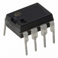
L6385 STMicroelectronics, L6385 Datasheet

L6385
Specifications of L6385
Available stocks
Related parts for L6385
L6385 Summary of contents
Page 1
... WITH HYSTERESIS AND PULL DOWN UNDER VOLTAGE LOCK OUT ON LOWER AND UPPER DRIVING SECTION INTERNAL BOOTSTRAP DIODE OUTPUTS IN PHASE WITH INPUTS DESCRIPTION The L6385 is an high-voltage device, manufac- tured with the BCD"OFF-LINE" technology. It has a Driver structure that enables to drive inde- BLOCK DIAGRAM BOOTSTRAP DRIVER V ...
Page 2
... L6385 ABSOLUTE MAXIMUM RATINGS Symbol Vout Output Voltage Vcc Supply Voltage Vboot Floating Supply Voltage Vhvg Upper Gate Output Voltage Vlvg Lower Gate Output Voltage Vi Logic Input Voltage dVout/dt Allowed Output Slew Rate Ptot Total Power Dissipation ( °C) Tj Junction Temperature Ts Storage Temperature ...
Page 3
... VIN = Vih (tp < VIN = Vil (tp < VIN = 15V VIN = CBOOT1 CC CBOOT2 DSON CC, CBOOT1 2 CC CBOOT2 , I when CBOOT1 2 CBOOT CBOOT2 L6385 Min. Typ. Max. Unit Note 1 580 V Note 400 kHz 17 V -45 125 °C Min. Typ. Max. Unit 110 ns 105 Min. Typ. Max. ...
Page 4
... A bootstrap circuitry is needed to supply the high voltage section. This function is normally accom- plished by a high voltage fast recovery diode (fig. 4a). In the L6385 a patented integrated structure replaces the external diode realized by a high voltage DMOS, driven synchronously with the low side driver (LVG), with in series a diode, as shown in fig ...
Page 5
... In fact: charge 30nC 0.8V V 125 ~ drop 5 s has to be taken into account when the volt- is calculated: if this drop is BOOT V BOOT H.V. HVG V OUT LVG b @ Vcc = 15V Typ. -45 - (°C) L6385 gate R dson C BOOT TO LOAD D99IN1056 100 125 5/9 ...
Page 6
... L6385 Figure Turn On Threshold vs. BOOT Temperature Typ -45 - (°C) Figure Turn Off Threshold vs. BOOT Temperature Typ -45 - Figure 9. Vcc UV Turn On Threshold vs. Temperature Typ -45 - (°C) 6/9 Figure 10. Vcc UV Turn Off Threshold vs Vcc = 15V 100 125 -45 Figure 11. Output Source Current vs. Tem- 1000 @ Vcc = 15V 800 ...
Page 7
... D 10.92 E 7.95 9.75 0.313 e 2.54 e3 7.62 e4 7.62 F 6.6 I 5.08 L 3.18 3.81 0.125 Z 1.52 inch TYP. MAX. 0.131 0.065 0.022 0.012 0.430 0.384 0.100 0.300 0.300 0.260 0.200 0.150 0.060 OUTLINE AND MECHANICAL DATA Minidip L6385 7/9 ...
Page 8
... L6385 mm DIM. MIN. TYP. MAX. MIN. A 1.35 1.75 0.053 A1 0.10 0.25 0.004 A2 1.10 1.65 0.043 B 0.33 0.51 0.013 C 0.19 0.25 0.007 (1) 4.80 5.00 0.189 D E 3.80 4.00 0.15 e 1.27 H 5.80 6.20 0.228 h 0.25 0.50 0.010 L 0.40 1.27 0.016 k 0˚ (min.), 8˚ (max.) ddd 0 ...
Page 9
... Australia – Belgium - Brazil - Canada - China – Czech Republic - Finland - France - Germany - Hong Kong - India - Israel - Italy - Japan - Malaysia - Malta - Morocco - Singapore - Spain - Sweden - Switzerland - United Kingdom - United States All other names are the property of their respective owners © 2003 STMicroelectronics - All rights reserved STMicroelectronics GROUP OF COMPANIES www.st.com L6385 9/9 ...


