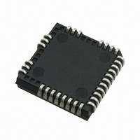
IRS2330DJPBF International Rectifier, IRS2330DJPBF Datasheet - Page 14

IRS2330DJPBF
Manufacturer Part Number
IRS2330DJPBF
Description
IC DVR 3-PHASE BRIDGE PLCC44
Manufacturer
International Rectifier
Datasheet
1.IRS2330JTRPBF.pdf
(36 pages)
Specifications of IRS2330DJPBF
Configuration
3 Phase Bridge
Input Type
Inverting
Delay Time
500ns
Current - Peak
250mA
Number Of Configurations
1
Number Of Outputs
3
High Side Voltage - Max (bootstrap)
600V
Voltage - Supply
10 V ~ 20 V
Operating Temperature
-40°C ~ 125°C
Mounting Type
Surface Mount
Package / Case
*
Lead Free Status / RoHS Status
Lead free / RoHS Compliant
Available stocks
Company
Part Number
Manufacturer
Quantity
Price
Company:
Part Number:
IRS2330DJPBF
Manufacturer:
International Rectifier
Quantity:
10 000
Fault Reporting
The IRS233(0,2)(D) family provides an integrated fault reporting output. There are two situations that would cause the HVIC
to report a fault via the FAULT pin. The first is an undervoltage condition of V
a fault. Once the fault condition occurs, the FAULT pin is internally pulled to V
output stays in the low state until the fault condition has been removed by all LINx set to high state. Once the fault is removed,
the voltage on the FAULT pin will return to V
Over-Current Protection
The IRS233(0,2)(D) HVICs are equipped with an ITRIP input pin. This functionality can be used to detect over-current events
in the DC- bus. Once the HVIC detects an over-current event through the ITRIP pin, the outputs are shutdown, a fault is
reported through the FAULT pin.
The level of current at which the over-current protection is initiated is determined by the resistor network (i.e., R
connected to ITRIP as shown in Figure 9, and the ITRIP threshold (V
maximum allowable level of current in the DC- bus and select R
over-current threshold (V
For example, a typical value for resistor R
V; if necessary, an external voltage clamp may be used.
Over-Temperature Shutdown Protection
The ITRIP input of the IRS233(0,2)(D) can also be used to detect over-temperature events in the system and initiate a
shutdown of the HVIC (and power switches) at that time. In order to use this functionality, the circuit designer will need to
design the resistor network as shown in Figure 10 and select the maximum allowable temperature.
This network consists of a thermistor and two standard resistors R
thermistor will change; this will result in a change of voltage at node V
voltage V
temperature is reached. The voltage of the ITRIP pin should not be allowed to exceed 5 V.
DL4148) can be used. This network is shown in Figure 11; the OR-ing diodes have been labeled D
When using both the over-current protection and over-temperature protection with the ITRIP input, OR-ing diodes (e.g.,
www.irf.com
X
should reach the threshold voltage (V
IT,TH+
) at that current level.
Figure 9: Programming the over-current protection
0
could be 50 mΩ. The voltage of the ITRIP pin should not be allowed to exceed 5
CC
.
V
IT,TH+
IT,TH+
R
1
HIN (x3)
LIN (x3)
FAULT
) of the ITRIP functionality by the time that the maximum allowable
ITRIP
= R
R
V
V
0
cc
SS
R
2
0
I
DC-
(R
0
3
1
, R
/(R
and R
1
I
DC-
1
, and R
IT,TH+
+R
X
4
2
. As the temperature changes, the resistance of the
. The resistor values should be selected such the
))
LO (x3)
). The circuit designer will need to determine the
COM
V
B
( x3)
CC
2
HO ( x3)
V
S
(x3)
such that the voltage at node V
SS
and the second is if the ITRIP pin recognizes
and the fault condition is latched. The fault
IRS233(0,2)(D)(S&J)PbF
1
and D
2
.
X
0
, R
reaches the
1
, and R
14
2
)


