IR2153 International Rectifier, IR2153 Datasheet - Page 2
IR2153
Manufacturer Part Number
IR2153
Description
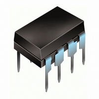
IC DRVR HALF BRDG SELF-OSC 8-DIP
Manufacturer
International Rectifier
Datasheet
1.IR2153SPBF.pdf
(9 pages)
Specifications of IR2153
Configuration
High and Low Side, Synchronous
Input Type
Self Oscillating
Current - Peak
200mA
Number Of Configurations
1
Number Of Outputs
2
High Side Voltage - Max (bootstrap)
600V
Voltage - Supply
10 V ~ 15.6 V
Operating Temperature
-40°C ~ 125°C
Mounting Type
Through Hole
Package / Case
8-DIP (0.300", 7.62mm)
Lead Free Status / RoHS Status
Contains lead / RoHS non-compliant
Delay Time
-
Other names
*IR2153
Available stocks
Company
Part Number
Manufacturer
Quantity
Price

Company:
Part Number:
IR2153-2
Manufacturer:
Agilent
Quantity:
1 000
Part Number:
IR21531
Manufacturer:
IR
Quantity:
20 000
Part Number:
IR21531D
Manufacturer:
IR
Quantity:
20 000
Part Number:
IR21531DPBF
Manufacturer:
IR
Quantity:
20 000
Part Number:
IR21531PBF
Manufacturer:
IR
Quantity:
20 000
Part Number:
IR21531S
Manufacturer:
IR
Quantity:
20 000


Recommended Operating Conditions
For proper operation the device should be used within the recommended conditions.
Note 1:
Note 2:
Note 3:
NOTE:For new designs, we recommend
IR’s new product IRS2153D
IR2153(D)(S) & (PbF)
Absolute Maximum Ratings
Absolute maximum ratings indicate sustained limits beyond which damage to the device may occur. All voltage param-
eters are absolute voltages referenced to COM, all currents are defined positive into any lead. The thermal resistance and
power dissipation ratings are measured under board mounted and still air conditions.
Symbol
Symbol
2
dV
Rth
V
V
V
V
V
V
I
V
I
V
V
I
P
T
CC
T
T
CC
T
RT
CC
HO
B
LO
RT
CT
s
S
D
J
B
S
S
J
L
s
/dt
JA
This IC contains a zener clamp structure between the chip V
voltage of 15.6V. Please note that this supply pin should not be driven by a DC, low impedance power source
greater than the V
Care should be taken to avoid output switching conditions where the V
more than 5V.
Enough current should be supplied to the V
voltage at this pin.
Definition
Definition
High side floating supply voltage
Steady state high side floating supply offset voltage
Supply voltage
Supply current
Junction temperature
High side floating supply voltage
High side floating supply offset voltage
High side floating output voltage
Low side output voltage
R
C
Supply current (note 1)
R
Allowable offset voltage slew rate
Maximum power dissipation @ T
Thermal resistance, junction to ambient
Junction temperature
Storage temperature
Lead temperature (soldering, 10 seconds)
T
T
T
pin voltage
pin voltage
pin current
CLAMP
specified in the Electrical Characteristics section.
A
≤ +25°C
CC
pin of the IC to keep the internal 15.6V zener diode clamping the
(8 Lead SOIC)
(8 Lead SOIC)
(8 Lead DIP)
(8 Lead DIP)
CC
and COM which has a nominal breakdown
S
-3.0 (note 2)
node flies inductively below ground by
V
(note 3)
V
V
CC
Min.
Min.
S
B
-0.3
-0.3
-0.3
-0.3
-40
-50
-55
-55
10
—
—
—
—
—
—
-5
- 0.3
- 25
- 0.7
V
V
V
V
V
V
V
Max.
Max.
CC
CC
CC
0.625
CLAMP
CLAMP
B
B
600
125
625
125
200
150
150
300
1.0
25
50
5
+ 0.3
+ 0.3
5
+ 0.3
+ 0.3
+ 0.3
www.irf.com
Units
Units
°C/W
V/ns
mA
°C
°C
mA
W
V
V
Related parts for IR2153
Image
Part Number
Description
Manufacturer
Datasheet
Request
R

Part Number:
Description:
SCHOTTKY RECTIFIER
Manufacturer:
International Rectifier Corp.
Datasheet:
Part Number:
Description:
SCHOTTKY RECTIFIER
Manufacturer:
International Rectifier Corp.
Datasheet:
Part Number:
Description:
SCHOTTKY RECTIFIER
Manufacturer:
International Rectifier Corp.
Datasheet:
Part Number:
Description:
SCHOTTKY RECTIFIER
Manufacturer:
International Rectifier Corp.
Datasheet:
Part Number:
Description:
SCHOTTKY RECTIFIER
Manufacturer:
International Rectifier Corp.
Datasheet:
Part Number:
Description:
SCHOTTKY RECTIFIER
Manufacturer:
International Rectifier Corp.
Datasheet:
Part Number:
Description:
SCHOTTKY RECTIFIER
Manufacturer:
International Rectifier Corp.
Datasheet:
Part Number:
Description:
SCHOTTKY RECTIFIER
Manufacturer:
International Rectifier Corp.
Datasheet:
Part Number:
Description:
SCHOTTKY RECTIFIER
Manufacturer:
International Rectifier Corp.
Datasheet:
Part Number:
Description:
SCHOTTKY RECTIFIER
Manufacturer:
International Rectifier Corp.
Datasheet:
Part Number:
Description:
SCHOTTKY RECTIFIER
Manufacturer:
International Rectifier Corp.
Datasheet:
Part Number:
Description:
SCHOTTKY RECTIFIER
Manufacturer:
International Rectifier Corp.
Datasheet:
Part Number:
Description:
SCHOTTKY RECTIFIER
Manufacturer:
International Rectifier Corp.
Datasheet:
Part Number:
Description:
SCHOTTKY RECTIFIER
Manufacturer:
International Rectifier Corp.
Datasheet:
Part Number:
Description:
SCHOTTKY RECTIFIER
Manufacturer:
International Rectifier Corp.
Datasheet: