MIC5015BM Micrel Inc, MIC5015BM Datasheet
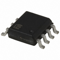
IC DRIVER MOSF HI/LOW SIDE 8SOIC

MIC5015BM

Manufacturer Part Number
MIC5015BM
Description
IC DRIVER MOSF HI/LOW SIDE 8SOIC
Manufacturer
Micrel Inc
Datasheet

Specifications of MIC5015BM

Mounting Type
Surface Mount
Configuration
High or Low Side
Input Type
Inverting
Delay Time
2.5ms
Number Of Configurations
1
Number Of Outputs
1
Voltage - Supply
2.75 V ~ 30 V
Operating Temperature
-40°C ~ 85°C
Package / Case
8-SOIC (3.9mm Width)
Device Type
MOSFET
Driver Case Style
SOIC
No. Of Pins
8
High Side Mosfet Drive Type
On-Chip Charge Pump
Rise Time
2.5ms
Load Voltage Max
30V
Supply Voltage Min
2.75V
Number Of Drivers
1
Driver Configuration
Inverting
Driver Type
High Side/Low Side
Input Logic Level
TTL
Operating Supply Voltage (max)
30V
Operating Supply Voltage (min)
2.75V
Turn Off Delay Time
30us
Turn On Delay Time (max)
8ms
Operating Temp Range
-40C to 85C
Operating Temperature Classification
Industrial
Mounting
Surface Mount
Pin Count
8
Package Type
SOIC
Lead Free Status / RoHS Status
Contains lead / RoHS non-compliant
Current - Peak
-
High Side Voltage - Max (bootstrap)
-
Lead Free Status / Rohs Status
Not Compliant

Available stocks

Company
Part Number
Manufacturer
Quantity
Price
Part Number:
MIC5015BM
Manufacturer:
MICREL
Quantity:
62
Part Number:
MIC5015BM
Manufacturer:
MICREL/麦瑞
Quantity:
20 000
MIC5014/5015
General Description
MIC5014 and MIC5015 MOSFET drivers are designed for
gate control of N-channel, enhancement-mode, power
MOSFETs used as high-side or low-side switches.
The MIC5014/5 can sustain an on-state output indefinitely.
The MIC5014/5 operates from a 2.75V to 30V supply. In high-
side configurations, the driver can control MOSFETs that
switch loads of up to 30V. In low-side configurations, with
separate supplies, the maximum switched voltage is limited
only by the MOSFET.
The MIC5014/5 has a TTL compatible control input.
The MIC5014 is noninverting while the MIC5015 is inverting.
The MIC5014/5 features an internal charge pump that can
sustain a gate voltage greater than the available supply
voltage. The driver is capable of turning on a logic-level
MOSFET from a 2.75V supply or a standard MOSFET from a
5V supply. The gate-to-source output voltage is internally
limited to approximately 15V.
The MIC5014/5 is protected against automotive load dump,
reversed battery, and inductive load spikes of –20V.
The driver’s overvoltage shutdown feature turns off the exter-
nal MOSFET at approximately 35V to protect the load against
power supply excursions.
The MIC5014 is an improved pin-for-pin compatible replace-
ment in many MIC5011 applications.
The MIC5014/5 is available in plastic 8-pin DIP and 8-pin
SOIC pacakges.
June 2005
Typical Application
Micrel, Inc. • 2180 Fortune Drive • San Jose, CA 95131 • USA • tel + 1 (408) 944-0800 • fax + 1 (408) 474-1000 • http://www.micrel.com
Figure 1. 3V “Sleep-Mode” Switch
OFF
ON
Control Input
with a Logic-Level MOSFET
10µF
1
2
3
4
V+
Input
Source
Gnd
MIC5014
Gate
NC
NC
NC
8
7
6
5
+3V to +4V
IRLZ24
1
Features
• 2.75V to 30V operation
• 100µA maximum supply current (5V supply)
• 15µA typical off-state current
• Internal charge pump
• TTL compatible input
• Withstands 60V transient (load dump)
• Reverse battery protected to –20V
• Inductive spike protected to –20V
• Overvoltage shutdown at 35V
• Internal 15V gate protection
• Minimum external parts
• Operates in high-side or low-side configurations
• 1µA control input pull-off
• Inverting and noninverting versions
Applications
• Automotive electrical load control
• Battery-powered computer power management
• Lamp control
• Heater control
• Motor control
• Power bus switching
Low-Cost High- or Low-Side MOSFET Driver
MIC5014/5015
MIC5014/5015
Micrel, Inc.

Related parts for MIC5015BM

MIC5015BM Summary of contents

Page 1

MIC5014/5015 General Description MIC5014 and MIC5015 MOSFET drivers are designed for gate control of N-channel, enhancement-mode, power MOSFETs used as high-side or low-side switches. The MIC5014/5 can sustain an on-state output indefinitely. The MIC5014/5 operates from a 2.75V to 30V ...

Page 2

... MIC5014/5015 Ordering Information Part Number Standard Pb-Free MIC5014BM MIC5014YM MIC5014BN MIC5014YN MIC5015BM MIC5015YM MIC5015BN MIC5015YN Block Diagram Input ( Only on the inverting version Pin Description Pin Number Pin Name Input 3 Source 4 Ground 5 Gate MIC5014/5015 Temperature Range Configuration –40ºC to +85ºC Non-Inverting – ...

Page 3

MIC5014/5015 Absolute Maximum Ratings Supply Voltage ............................................... –20V to 60V Input Voltage ..................................................... –20V to V Source Voltage ..................................................–20V to V Source Current .......................................................... 50mA Gate Voltage .................................................. –20V to 50V Junction Temperature .............................................. 150°C Electrical Characteristics Parameter Supply Current ...

Page 4

MIC5014/5015 Typical Characteristics All data measured using FET probe to minimize resistive loading Supply Current (Output Asserted SUPPLY VOLTAGE (V) High-Side Turn-On Time Until Gate = ...

Page 5

MIC5014/5015 Applications Information Functional Description The MIC5014 is functionally and pin for pin compatible with the MIC5011, except for the omission of the optional speed- up capacitor pins, which are available on the MIC5011. The MIC5015 is an inverting configuration ...

Page 6

MIC5014/5015 Low Side Driver (Figure 2) A key advantage of this topology, as previously mentioned, is speed. The MOSFET gate is driven to near supply immediately when the MIC5014/15 is turned on. Typical circuits reach full enhancement in 50µs or ...

Page 7

MIC5014/5015 10µF 1kΩ Figure 5. High Side Driver with Delayed Overcurrent Shutdown Typical Applications Variable Supply Low Side Driver for Motor Speed Control (Figure 6) The internal regulation in the MIC5014/15 allows a steady gate enhancement to be supplied while ...

Page 8

MIC5014/5015 Incandescent/Halogen Lamp Driver (Figure 8) The combi- nation of an MIC5014/5015 and a power FET makes an effective driver for a standard incandescent or halogen lamp load. Such loads often have high inrush currents, as the resistance of a ...

Page 9

MIC5014/5015 High Side Driver With Load Protection (Figure 12) Al- though the MIC5014/15 devices are reverse battery pro- tected, the load and power FET are not typical high side configuration. In the event of a reverse battery condition, ...

Page 10

MIC5014/5015 Package Information 0.018 (0.57) 0.026 (0.65) 0.157 (3.99) 0.150 (3.81) 0.064 (1.63) 0.045 (1.14) MIC5014/5015 PIN 1 DIMENSIONS: INCH (MM) 0.380 (9.65) 0.370 (9.40) 0.135 (3.43) 0.125 (3.18) 0.380 (9.65) 0.130 (3.30) 0.320 (8.13) 0.100 (2.54) 0.0375 (0.952) 8-Pin ...

Page 11

MIC5014/5015 June 2005 11 Micrel, Inc. MIC5014/5015 ...

Page 12

... MIC5014/5015 MICREL INC. 2180 FORTUNE DRIVE SAN JOSE, CA 95131 USA + 1 (408) 944-0800 TEL This information furnished by Micrel in this data sheet is believed to be accurate and reliable. However no responsibility is assumed by Micrel for its use. Micrel reserves the right to change circuitry and specifications at any time without notification to the customer. ...

Related keywords