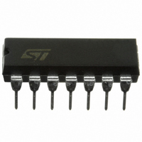
L6386 STMicroelectronics, L6386 Datasheet

L6386
Specifications of L6386
Available stocks
Related parts for L6386
L6386 Summary of contents
Page 1
... WITH HYSTERESIS AND PULL DOWN UNDER VOLTAGE LOCK OUT ON LOWER AND UPPER DRIVING SECTION INTEGRATED BOOTSTRAP DIODE OUTPUTS IN PHASE WITH INPUTS DESCRIPTION The L6386 is an high-voltage device, manufac- tured with the BCD "OFF-LINE" technology. It has a Driver structure that enables to drive inde- BLOCK DIAGRAM BOOTSTRAP DRIVER V ...
Page 2
... L6386 ABSOLUTE MAXIMUM RATINGS Symbol Vout Output Voltage Vcc Supply Voltage Vboot Floating Supply Voltage Vhvg Upper Gate Output Voltage Vlvg Lower Gate Output Voltage Vi Logic Input Voltage Vdiag Open Drain Forced Voltage Vcin Comparator Input Voltage dVout/dt Allowed Output Slew Rate Ptot Total Power Dissipation ( ° ...
Page 3
... VIN = Vih (tp < VIN = 15V VIN = CBOOT1 CBOOT2 DSON CC, CBOOT1 2 CC CBOOT2 , I when CBOOT1 2 CBOOT CBOOT2 L6386 Min. Typ. Max. Unit Note1 580 V Note1 17 V 400 kHz 17 V -45 125 °C Min. Typ. Max. Unit 110 150 ns 105 150 ns 105 150 ns 50 ...
Page 4
... L6386 DC OPERATION (continued) Symbol Pin Parameter Sense Comparator Vio Input Offset Voltage Iio 6 Input Bias Current Vol 2 Open Drain Low Level Output Voltage, Iod = -2.5mA Vref Comparator Reference voltage Figure 1. Timing Waveforms HIN LIN SD HOUT LOUT V REF V CIN DIAG Note: SD active condition is latched until next negative IN edge. ...
Page 5
... A bootstrap circuitry is needed to supply the high voltage section. This function is normally accom- plished by a high voltage fast recovery diode (fig. 4a). In the L6386 a patented integrated structure replaces the external diode realized by a high voltage DMOS, driven synchronously with the low side driver (LVG), with in series a diode, as shown in fig ...
Page 6
... L6386 Figure 5. Turn On Time vs. Temperature 250 200 150 Typ. 100 50 0 -45 - (°C) Figure 6. Turn Off Time vs. Temperature 250 200 150 Typ. 100 50 0 -45 - (°C) Figure 7. Shutdown Time vs. Temperature 250 200 150 Typ. 100 50 0 -45 - (°C) 6/10 Figure Vcc = 15V 100 125 -45 Figure 9 ...
Page 7
... Figure 14. Output Source Current vs. Tem- 1000 800 600 Typ. 400 200 0 75 100 125 -45 Figure 15. Output Sink Current vs. Tempera- 1000 800 Typ. 600 400 200 0 -45 75 100 125 75 100 125 perature @ Vcc = 15V - 100 125 Tj (°C) ture @ Vcc = 15V - 100 125 Tj (°C) L6386 7/10 ...
Page 8
... L6386 mm DIM. MIN. TYP. MAX. MIN. a1 0.51 0.020 B 1.39 1.65 0.055 b 0 8.5 e 2.54 e3 15.24 F 7.1 I 5.1 L 3.3 Z 1.27 2.54 0.050 8/10 inch MECHANICAL DATA TYP. MAX. 0.065 0.020 0.010 0.787 0.335 0.100 0.600 0.280 0.201 0.130 0.100 OUTLINE AND ...
Page 9
... D and F do not include mold flash or protrusions. Mold flash or potrusions shall not exceed 0.15mm (.006inch). inch TYP.. MAX.. MECHANICAL DATA 0.069 0.009 0.063 0.018 0.010 0.020 0.344 0.244 0.050 0.300 0.157 0.209 0.050 0.027 L6386 OUTLINE AND SO14 9/10 ...
Page 10
... L6386 Information furnished is believed to be accurate and reliable. However, STMicroelectronics assumes no responsibility for the consequences of use of such information nor for any infringement of patents or other rights of third parties which may result from its use. No license is granted by implication or otherwise under any patent or patent rights of STMicroelectronics. Specification mentioned in this publication are subject to change without notice ...


