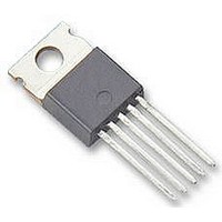
BTS555 Infineon Technologies, BTS555 Datasheet

BTS555
Specifications of BTS555
SP000011266
Available stocks
Related parts for BTS555
BTS555 Summary of contents
Page 1
... TO-218AB/5 Straight leads Current Overvoltage Gate limit protection protection Limit for Charge pump unclamped ind. loads Level shifter Rectifier Output Voltage Logic detection Temperature sensor PROFET ® Data Sheet BTS555 Reversave V bb(AZ) V ON(CL) V 5.0 ... 34 bb(on L(ISO) L(SCp 000 TO-218AB-5 Staggered leads 3 & ...
Page 2
... Truth Table on page 7) Output to the load. The pins 1 and 5 must be shorted with each other especially in high current applications! T =-40 .+150°C: j,start = 13 °C = 150°C const., C see diagrams on page 10 2 Data Sheet BTS555 4 ) connection bb 4) Symbol Values self-limited ...
Page 3
... 150 ° 1 ° 1 150 ° 90 OUT 10 OUT ) dV/dt OUT ) -dV/dt OUT increase is less than 10 % per second for T 3 Data Sheet BTS555 Symbol Values min typ ) thJC 30 -- thJA Symbol Values min typ 4.6 ON(Static) 128 165 L(ISO) 520 -- L(Max) 360 -- 120 ...
Page 4
... 25...+150° =-40...+25° 150°C: j -decrease, the operating voltage range is extended down increases from less than V bIN OUT bb 4 Data Sheet BTS555 Symbol Values min typ 1) -- 1.9 ON(inv) 3.3 128 165 L(inv) -- 0.6 ON 5.0 -- bb(on) 1.5 3.0 bIN(u) 3 ...
Page 5
... T =+150° d(SC mA ON(CL) V ON(SC ° 150 ° ° 150 ° inductive load switch off. bb ON(CL) 5 Data Sheet BTS555 Values min typ 200 320 200 400 300 480 OUT(CL 150 -- -- 2.3 -- ON(rev) 3.9 90 110 bb 105 125 = the power transistor IN ...
Page 6
... T =150° =-40° 25...+150° Data Sheet BTS555 Symbol Values min typ 25 000 29 000 34 000 ILIS 26 000 28 500 32 000 24 000 26 500 29 000 25 000 31 200 40 000 25 000 30 200 35 000 23 000 27 200 31 500 24 000 33 500 48 000 24 000 31 500 40 000 23 000 27 500 32 000 ...
Page 7
... =low and T j < (see diagram on page14 OUT 1 OUT R IS and can thus be detected via the sense current Data Sheet BTS555 Remark = ilis IS IS,lim ON(Fold back) no longer proportional > ON(Fold back) >V , shutdown will occure ON(SC) measurement layout (straight leads) 5 force contacts Out Force ...
Page 8
... V . Overvoltage protection of logic part ilis can reach 120 bb nominal. Note that when overvoltage exceeds 71 V typ. a voltage above 5V can occur between IS and GND Z,VIS 8 Data Sheet BTS555 > typ.) and t> t ON(SC) ON Short circuit Logic detection unit PROFET typ. At inductive load ON(Cl) ...
Page 9
... Power GND using a diode without additional Z-diode V Version c: Sometimes a neccessary voltage clamp is for reverse IN given by non inductive loads R above bb switch and eliminates the need of clamping circuit 0. 12V and < OUT Data Sheet BTS555 V bb OUT IN PROFET IS Zb connected to the same OUT IN PROFET IS 2008-June- ...
Page 10
... T1 will be reset. The device is turned on again the short circuit current is defined device is shut down after · i (t) dt, ON(CL Signal · ( OUT(CL) 10 Data Sheet BTS555 100 100 *R . After a delay time defined L(SC) with latch function. d(SC PROFET OUT Signal GND 2008-June-24 1000 I L [A] and the R load R ...
Page 11
... Can be "switched off" by using a diode D 26 Infineon Technologies AG BTS 6510 550P 650P 26 < V after shutdown. In most cases V ON(SC) (see page 8) or leaving open the current sense output Data Sheet BTS555 555 26 after shutdown (V OUT < V (see page 5). No latch bb ON(SC) 2008-June-24 OUT ...
Page 12
... I [A] L Current sense ratio f(I ILIS k ilis 65000 60000 55000 50000 45000 40000 35000 30000 25000 20000 150 I [ Data Sheet BTS555 ), ° max typ min 0 50 100 ), T = 150 ° max typ min 0 50 100 2008-June-24 150 I [A] L 150 ...
Page 13
... Typ. on-state resistance [mOhm 150° 85°C 25°C 2 -40° Infineon Technologies AG Typ. input current bIN I [mA] IN 1.6 1.4 1.2 only for t < t d(SC) 1.0 0.8 25°C 0.6 0.4 150° static dynamic [ Data Sheet BTS555 ), bIN = 2008-June- [V] bIN ...
Page 14
... Infineon Technologies AG Figure 2b: Switching an inductive load dV/dtoff V OUT t off t slc(IS soff(IS) Figure 3a: Short circuit: shut down by short circuit detection, reset Shut down remains latched until next reset via input. 14 Data Sheet BTS555 IN I L(SCp) t d(SC) V >>0 OUT V =0 OUT 2008-June- ...
Page 15
... Figure 4a: Overtemperature, Reset if (I =low) and (T < OUT T J Figure 6a: Undervoltage restart of charge pump, overvoltage clamp V OUT V IN dynamic, short 6 Undervoltage not below V bIN( bIN(u) bIN(ucp) Infineon Technologies ON(CL ON(CL) 15 Data Sheet BTS555 2008-June-24 ...
Page 16
... If they fail reasonable to assume that the health of the user or other persons may be endangered. +0.15 0.5 4.5 ±0.3 8.2 ±0 P-TO218-5-1-PO V01 16 Data Sheet BTS555 Changes Package drawings updated Revision history added Legal disclaimer updated 2008-June-24 ...


