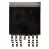
BTS621L1 E3128A Infineon Technologies, BTS621L1 E3128A Datasheet - Page 2

BTS621L1 E3128A
Manufacturer Part Number
BTS621L1 E3128A
Description
IC SW PWR HISIDE TO-220AB/7 SMD
Manufacturer
Infineon Technologies
Series
PROFET®r
Type
High Sider
Datasheet
1.BTS621L1_E3128A.pdf
(16 pages)
Specifications of BTS621L1 E3128A
Input Type
Non-Inverting
Number Of Outputs
2
On-state Resistance
80 mOhm
Current - Output / Channel
4.4A
Current - Peak Output
14A
Voltage - Supply
5 V ~ 34 V
Operating Temperature
-40°C ~ 150°C
Mounting Type
Surface Mount
Package / Case
TO-220-7 (Bent Leads)
Lead Free Status / RoHS Status
Contains lead / RoHS non-compliant
Other names
BTS621L1 E3128A
BTS621L1E3128AINTR
BTS621L1E3128ANT
BTS621L1E3128AT
SP000011281
BTS621L1E3128AINTR
BTS621L1E3128ANT
BTS621L1E3128AT
SP000011281
Maximum Ratings at T
Parameter
Supply voltage (overvoltage protection see page 4)
Supply voltage for full short circuit protection
T
Load dump protection
Load current (Short circuit current, see page 5)
Operating temperature range
Storage temperature range
Power dissipation (DC), T
Inductive load switch-off energy dissipation, single pulse
Electrostatic discharge capability (ESD)
Input voltage (DC)
Current through input pin (DC)
Current through status pin (DC)
see internal circuit diagrams page 7
2
3)
4)
Semiconductor Group
)
R
V
see diagrams on page 9
(Human Body Model)
acc. MIL-STD883D, method 3015.7 and ESD assn. std. S5.1-1993
Pin
1
2
3
4
5
6
7
j Start
bb
I
3
Supply voltages higher than V
150
protection of the input is integrated.
R
V
)
= 2
Load dump
I
= 12V, T
=-40 ...+150°C
= internal resistance of the load dump test pulse generator
both channels parallel, I
resistor in the GND connection and a 15 k
, R
Symbol
OUT1 (Load, L)
GND
IN1
V bb
ST
IN2
OUT2 (Load, L)
is setup without the DUT connected to the generator per ISO 7637-1 and DIN 40839
L
j,start
= 2.7
one channel, I
= 150°C, T
, t
2
)
d
V
= 200 ms, IN= low or high
j
= 25 °C unless otherwise specified
LoadDump
C
C
bb(AZ)
25 °C
L
= 150°C const.
L
= 4.4 A, Z
= 8.5 A, Z
Function
Output 1, protected high-side power output of channel 1
Logic ground
Input 1, activates channel 1 in case of logical high signal
Positive power supply voltage,
the tab is shorted to this pin
Diagnostic feedback: open drain, low on failure
Input 2, activates channel 2 in case of logical high signal
Output 2, protected high-side power output of channel 2
require an external current limit for the GND and status pins, e.g. with a
= U
A
+ V
L
L
= 32 mH, 0
s
= 17 mH, 0
, U
all other pins:
2
resistor in series with the status pin. A resistor for the
A
= 13.5 V
IN:
:
:
V
V
V
I
T
T
P
E
V
V
I
I
Symbol
L
IN
ST
bb
Load dump
j
stg
bb
tot
AS
ESD
IN
PROFET ® BTS621L1
4
)
self-limited
-40 ...+150
-55 ...+150
-10 ... +16
Values
2003-Oct-01
395
790
1.0
2.0
2.0
5.0
43
34
60
75
Unit
mA
mJ
kV
°C
W
V
V
V
A
V


