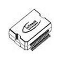
TLE6230GP Infineon Technologies, TLE6230GP Datasheet

TLE6230GP
Specifications of TLE6230GP
SP000691114
TLE6230GP
TLE6230GPNT
TLE6230GPT
TLE6230GPT
TLE6230GPTR
Available stocks
Related parts for TLE6230GP
TLE6230GP Summary of contents
Page 1
Smart Octal Low-Side Switch Features Product Summary • Short Circuit Protection • Overtemperature Protection • Overvoltage Protection • 16 bit Serial Data Input and Diagnos- tic Output (2 bit/ch. acc. SPI protocol) • Direct Parallel Control of Four Channels for ...
Page 2
Block Diagram RESET GND VS PRG IN1 & IN2 & IN3 & IN4 & SO SPI SI Interface 16 bit SCLK CS V2.3 Detailed Block Diagram VS FAULT Channel 1 Normal function SCB/Overload Open load short to ground Output Stage ...
Page 3
Pin Description Pin Symbol 1 GND Ground 2 NC not connected 3 NC not connected 4 OUT1 Power Output Channel 1 5 OUT2 Power Output Channel 2 6 IN1 Input Channel 1 7 IN2 Input Channel Supply ...
Page 4
Maximum Ratings for T j Parameter Supply Voltage Continuous Drain Source Voltage (OUT1...OUT8) Input Voltage, All Inputs and Data Lines Load Dump Protection V Load Dump = 70 Ω With Automotive Relay Load Ω ...
Page 5
Electrical Characteristics Parameter and Conditions V = 4 ° 150 °C ; Reset = (unless otherwise specified) 1. Power Supply, Reset 4 Supply Voltage 5 Supply Current ...
Page 6
Electrical Characteristics cont. Parameter and Conditions V = 4 ° 150 °C ; Reset = (unless otherwise specified) 5. Diagnostic Functions Open Load Detection Voltage Output Pull ...
Page 7
Functional Description The TLE 6230 octal-low-side power switch which provides a serial peripheral inter- face (SPI) to control the 8 power DMOS switches, as well as diagnostic feedback. The power transistors are protected against short to V ...
Page 8
Power Transistor Protection Functions Each of the eight output stages has its own zener clamp, which causes a voltage limitation at the power transistor when solenoid loads are switched off. The outputs are provided with a current limitation set to ...
Page 9
SO - Serial Output. Diagnostic data bits are shifted ...
Page 10
A definite distinction between open load and short to ground is guaranteed by design. The standard way of obtaining diagnostic information is as follows: Clock in serial information into SI pin and wait approximately 150 µs to allow the outputs ...
Page 11
CS SCLK MSB Figure 2: Serial Interface Figure 3: Input Timing Diagram CS 0 SCKH t lead SCLK Figure 4: 0.7 V ...
Page 12
80% 20% Figure 5: Power Outputs Timing is valid for resistive load with parallel and serial control. Rising edge of chip select initiates the switching Application Circuits µC e.g. ...
Page 13
Typical electrical Characteristics Drain-Source on-resistance DS(ON Typical Drain- Source ON-Resistance 1,5 1,4 1,3 1,2 1,1 1 0,9 0,8 0,7 0,6 0,5 0,4 -50 -25 0 Typical ON Resistance versus ...
Page 14
Maximum single clamp Energy 300 250 200 150 100 0,2 Maximum Clamp Energy (single event) versus Peak Current Figure 8 : Channel 1-8 Parallel SPI Configuration 4 P x.1 Channels MTSR SI SO MRST ...
Page 15
Package and Ordering Code (all dimensions in mm) PG-DSO 36 TLE 6230 GP V2.3 Data Sheet TLE 6230 GP Page 15 18. Nov. 2009 ...
Page 16
... Infineon Technologies Office. Infineon Technologies components may be used in life-support devices or systems only with the ex- press written approval of Infineon Technologies failure of such components can reasonably be ex- pected to cause the failure of that life-support device or system or to affect the safety or effectiveness of that device or system ...


