ISL6571CRZ Intersil, ISL6571CRZ Datasheet
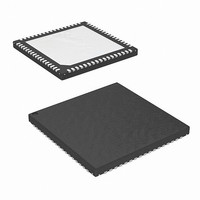
IC MOSF DRVR/SYNC SW COMPL 68QFN

ISL6571CRZ

Manufacturer Part Number
ISL6571CRZ
Description
IC MOSF DRVR/SYNC SW COMPL 68QFN
Manufacturer
Intersil
Type
Half Bridger
Datasheet

Specifications of ISL6571CRZ

Input Type
PWM
Current - Output / Channel
25A
Voltage - Supply
10.8 V ~ 13.2 V
Operating Temperature
0°C ~ 70°C
Mounting Type
Surface Mount
Package / Case
68-VQFN Exposed Pad, 68-HVQFN, 68-SQFN, 68-DHVQFN
Lead Free Status / RoHS Status
Lead free / RoHS Compliant
Number Of Outputs
-
On-state Resistance
-
Current - Peak Output
-
Complementary MOSFET Driver and
Synchronous Half-Bridge Switch
The Intersil ISL6571 provides a new approach for
implementing a synchronous rectified buck switching
regulator. The ISL6571 replaces two power MOSFETs, a
Schottky diode, two gate drivers and synchronous control
circuitry. Its main applications address high-density power
conversion circuits including multiphase-topology computer
microprocessor core power regulators, ASIC and memory
array regulators, etc. Another useful feature of the ISL6571
is the compatibility with three-state input control: left open,
the PWM input turns off both output drives. The ISL6571
operates in continuous conduction mode reducing EMI
constraints and enabling high bandwidth operation.
Ordering Information
ISL6571CR*
ISL6571CRZ*
(See Note)
ISL6571EVAL1
*Add “-T” suffix for tape and reel.
NOTE: Intersil Pb-free products employ special Pb-free material
sets; molding compounds/die attach materials and 100% matte tin
plate termination finish, which are RoHS compliant and compatible
with both SnPb and Pb-free soldering operations. Intersil Pb-free
products are MSL classified at Pb-free peak reflow temperatures that
meet or exceed the Pb-free requirements of IPC/JEDEC J STD-020.
PART NUMBER
Evaluation Board
RANGE (°C)
0 to 70
0 to 70
TEMP.
®
1
68 Ld 10x10 QFN L68.10x10A
68 Ld 10x10 QFN
(Pb-free)
PACKAGE
Data Sheet
L68.10x10A
DWG. #
PKG.
1-888-INTERSIL or 1-888-352-6832
CAUTION: These devices are sensitive to electrostatic discharge; follow proper IC Handling Procedures.
Features
• Improved Performance over Conventional Synchronous
• Optimal Deadtime Provided by Adaptive Shoot-Through
• Switching Frequency up to 1MHz
• Reduced Connection Parasitics between Discrete
• Low Profile, Low Thermal Impedance Packaging
• QFN Package:
• Pb-Free Available (RoHS Compliant)
Applications
• Multiphase Power Regulators
• Low-Voltage Switchmode Power Conversion
• High-Density Power Converters
Buck Converter using Discrete Components
- High-Bandwidth, Fast Transient Response
- Small, Low Profile Converters
Components
- Low Electromagnetic Emissions
- High Power Density Applications
- Compliant to JEDEC PUB95 MO-220
- Near Chip Scale Package footprint, which improves
QFN - Quad Flat No Leads - Package Outline
PCB efficiency and has a thinner profile
All other trademarks mentioned are the property of their respective owners.
April 18, 2005
|
Intersil (and design) is a registered trademark of Intersil Americas Inc.
Copyright Intersil Americas Inc. 2003-2005. All Rights Reserved
ISL6571
FN9082.4

Related parts for ISL6571CRZ

ISL6571CRZ Summary of contents

Page 1

... Ordering Information TEMP. PART NUMBER RANGE (°C) PACKAGE ISL6571CR 10x10 QFN L68.10x10A ISL6571CRZ 10x10 QFN (See Note) (Pb-free) ISL6571EVAL1 Evaluation Board *Add “-T” suffix for tape and reel. NOTE: Intersil Pb-free products employ special Pb-free material sets ...

Page 2

Pinout PHASE 1 PHASE 2 3 PHASE PHASE 4 5 PHASE PHASE 6 PHASE 7 PHASE 8 PHASE 9 PHASE 10 PHASE 11 12 PHASE 13 PHASE 14 PHASE PHASE 15 PHASE 16 PHASE 17 2 ISL6571 ISL6571 (QFN) TOP ...

Page 3

VCC POWER-ON RESET (POR) + CONTROL 5V LOGIC - 10K PWM 10K GND PVCC DRIVE1 GATE CONTROL PVCC DRIVE2 LGATE1 FIGURE 1. BLOCK DIAGRAM VIN BOOT UFET PHASE LGATE LFET PGND ...

Page 4

PWM +12VIN +5VIN 20 VCC PWM4 PWM1 18 ISEN4 ISEN1 17 PWM2 POWER GOOD 19 PGOOD ISEN2 U1 HIP6301 8 FS/DIS PWM3 R FS ISEN3 COMP 5 VID0 4 VID1 3 VID2 2 VID3 1 VID4 FB GND ...

Page 5

Absolute Maximum Ratings Bias Supply Voltage, VCC . . . . . . . . . . . . . . . . . . . . . . . . . . . . .+15V Driver Supply, PVCC . ...

Page 6

Typical Performance Curves/Setup +12V +5V C PVCC +12V C VCC VCC PVCC BOOT VIN CONTROL PWM AND PHASE DRIVERS ISL6571 GND PGND FIGURE 4. TYPICAL TEST CIRCUIT 126 PVCC 108 V = 10V PVCC ...

Page 7

Typical Performance Curves/Setup FIGURE 10. ISL6571 EFFICIENCY AT 200kHz, 300kHz, 500kHz, 750kHz Functional Pin Descriptions VCC (Pin 54) Provide a 12V bias supply for the driver IC to this pin. The voltage at this pin is monitored for Power-On Reset ...

Page 8

VCC pin. The higher the voltage applied at the PVCC pin, the better the channel enhancement of the on- board power MOSFETs, but also the higher ...

Page 9

... Accordingly, the reader is cautioned to verify that data sheets are current before placing orders. Information furnished by Intersil is believed to be accurate and reliable. However, no responsibility is assumed by Intersil or its subsidiaries for its use; nor for any infringements of patents or other rights of third parties which may result from its use ...

Page 10

C 20 VCC 15 PWM1 16 ISEN1 PWM2 ISEN2 POWER PWM3 GOOD 19 PGOOD > ISEN3 U1 HIP6301 8 FS/DIS PWM4 R ISEN4 FS COMP 5 VID0 4 VID1 3 VID2 2 VID3 ...

Page 11

Quad Flat No-Lead Plastic Package (QFN) Micro Lead Frame Plastic Package (MLFP D INDEX AREA 0. TOP VIEW 0. θ C SEATING SIDE VIEW PLANE ...

Related keywords