A3968SLBTR-T Allegro Microsystems Inc, A3968SLBTR-T Datasheet
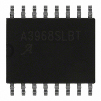
IC MOTOR DRIVER PWM DUAL 16SOIC

A3968SLBTR-T

Manufacturer Part Number
A3968SLBTR-T
Description
IC MOTOR DRIVER PWM DUAL 16SOIC
Manufacturer
Allegro Microsystems Inc
Datasheet

Specifications of A3968SLBTR-T

Applications
PWM Motor Driver
Number Of Outputs
2
Current - Output
±650mA
Voltage - Load
4.75 V ~ 30 V
Voltage - Supply
4.75 V ~ 5.5 V
Operating Temperature
-20°C ~ 85°C
Mounting Type
Surface Mount
Package / Case
16-SOIC (0.300", 7.5mm Width)
Motor Type
Full Bridge
No. Of Outputs
2
Output Current
650mA
Output Voltage
30V
Supply Voltage Range
4.75V To 5.5V
Driver Case Style
SOIC
No. Of Pins
16
Lead Free Status / RoHS Status
Lead free / RoHS Compliant
Other names
620-1141-2
A3968SLBTR-T

Available stocks

Company
Part Number
Manufacturer
Quantity
Price
Part Number:
A3968SLBTR-T
Manufacturer:
ALLEGRO/雅丽高
Quantity:
20 000
Features and Benefits
▪ ±650 mA continuous output current
▪ 30 V output voltage rating
▪ Internal fixed-frequency PWM current control
▪ Satlington® sink drivers
▪ Brake mode
▪ User-selectable blanking window
▪ Internal ground-clamp and flyback diodes
▪ Internal thermal-shutdown circuitry
▪ Crossover-current protection and UVLO protection
Package: 16 pin SOIC (suffix LB)
Not to scale
29319.29G
MOTOR
+5 V
1
INPUT
INPUT
+24 V
47 μF
1B
1A
0.5 Ω
Dual Full-Bridge PWM Motor Driver
Typical Application
1
2
3
4
5
6
7
8
V
REF
LOGIC
Dwg. EP-047-6
V
BB
V
BB
Continued on the next page…
LOGIC
Description
The A3968 bidirectionally controls two DC motors. The device
includes two full-bridges capable of continuous output currents
of ±650 mA and operating voltages to 30 V. Motor winding
current can be controlled by the internal fixed-frequency,
pulse-width modulated (PWM), current-control circuitry. The
peak load current limit is set by user selection of a reference
voltage and current-sensing resistors.
The fixed-frequency pulse duration is set by a user-selected
external RC timing network. The capacitor in the RC timing
network also determines a user-selectable blanking window that
prevents false triggering of the PWM current-control circuitry
during switching transitions.
To reduce on-chip power dissipation, the full-bridge power
outputs have been optimized for low saturation voltages. The
sink drivers feature the Allegro
structure. The Satlington outputs combine the low voltage drop
of a saturated transistor and the high peak current capability
of a Darlington.
For each bridge, the INPUT
the load-current polarity by enabling the appropriate source and
sink driver pair. When a logic low is applied to both INPUTs
V
CC
RC
16
15
14
13
12
11
10
9
0.5 Ω
INPUT
INPUT
+5 V
2A
2B
A
MOTOR
and INPUT
®
patented Satlington
2
B
terminals determine
A3968
®
output

Related parts for A3968SLBTR-T

A3968SLBTR-T Summary of contents

Page 1

Features and Benefits ▪ ±650 mA continuous output current ▪ output voltage rating ▪ Internal fixed-frequency PWM current control ▪ Satlington® sink drivers ▪ Brake mode ▪ User-selectable blanking window ▪ Internal ground-clamp and flyback diodes ▪ Internal ...

Page 2

... INPUTs of a bridge, all output drivers are disabled. Special power-up sequencing is not required. Internal circuit protection includes thermal shutdown with hysteresis, ground-clamp Selection Guide Part Number A3968SLBTR–T Absolute Maximum Ratings Characteristic Load Supply Voltage Logic Supply Voltage Input Voltage ...

Page 3

A3968 Dual Full-Bridge PWM Motor Driver with Brake INPUT A UVLO & TSD INPUT B GROUND INPUT Z = High impedance FUNCTIONAL BLOCK DIAGRAM (One Half of Circuit Shown BLANKING CURRENT-SENSE GATE COMPARATOR PWM LATCH ...

Page 4

A3968 Dual Full-Bridge PWM Motor Driver with Brake Ω Load Supply Voltage Range Output Leakage Current Output Saturation Voltage Clamp Diode Forward Voltage Motor Supply Current (No Load) Logic Supply Voltage Range Logic Input Voltage Logic Input Current Reference Input ...

Page 5

A3968 Dual Full-Bridge PWM Motor Driver with Brake Ω (continued) PWM RC Frequency PWM Propagation Delay Time Cross-Over Dead Time Propagation Delay Times Thermal Shutdown Temp. Thermal Shutdown Hysteresis UVLO Enable Threshold UVLO Hysteresis V Logic Supply Current I NOTES:1. ...

Page 6

A3968 Dual Full-Bridge PWM Motor Driver with Brake Internal PWM Current Control. full-bridges bidirectionally control two DC motors. A internal fi xed-frequency PWM control circuit controls the the load current in each motor. The current-control circuitry works as follows: when ...

Page 7

A3968 Dual Full-Bridge PWM Motor Driver with Brake Load Current Regulation. Due to internal logic and switching delays the actual load current peak will be d slightly higher than the I value. These delays, plus the TRIP blanking ...

Page 8

A3968 Dual Full-Bridge PWM Motor Driver with Brake 10.30±0. 16X 0.10 C 0.41 ±0.10 1.27 For Reference Only Pins 4 and 13 internally fused Dimensions in millimeters (reference JEDEC MS-013 AA) Dimensions exclusive of mold flash, ...

Related keywords