L6228N STMicroelectronics, L6228N Datasheet - Page 5
L6228N
Manufacturer Part Number
L6228N
Description
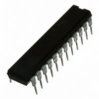
IC DRIVER STEPPER MOTOR 24PWRDIP
Manufacturer
STMicroelectronics
Type
Driverr
Datasheet
1.L6228DTR.pdf
(26 pages)
Specifications of L6228N
Applications
Stepper Motor Driver
Number Of Outputs
1
Current - Output
1.4A
Voltage - Supply
8 V ~ 52 V
Operating Temperature
-25°C ~ 125°C
Mounting Type
Through Hole
Package / Case
24-DIP (0.300", 7.62mm)
Product
Stepper Motor Controllers / Drivers
Operating Supply Voltage
8 V to 52 V
Supply Current
1.4 A
Mounting Style
Through Hole
Motor Type
Stepper
No. Of Outputs
4
Output Current
3.55A
Output Voltage
52V
Supply Voltage Range
8V To 52V
Driver Case Style
DIP
No. Of Pins
24
Operating Temperature Range
-40°C To +150°C
Rohs Compliant
Yes
For Use With
497-6818 - EVAL BOARD FOR L6228Q
Lead Free Status / RoHS Status
Lead free / RoHS Compliant
Voltage - Load
-
Lead Free Status / Rohs Status
Lead free / RoHS Compliant
Other names
497-5350-5
L6228N
L6228N
Available stocks
Company
Part Number
Manufacturer
Quantity
Price
Company:

Part Number:
L6228N
Manufacturer:
STMicroelectronics
Quantity:
740
Part Number:
L6228N
Manufacturer:
ST
Quantity:
20 000


PIN DESCRIPTION (continued)
(6)
ELECTRICAL CHARACTERISTICS
(T
Output DMOS Transistors
Source Drain Diodes
Logic Inputs (EN, CONTROL, HALF/FULL, CLOCK, RESET, CW/CCW)
V
PowerDIP24
Symbol
V
R
amb
T
Sth(OFF)
Sth(ON)
DS(ON)
I
V
j(OFF)
SO24/
V
DSS
V
PIN #
I
I
I
t
t
IH
SD
IL
S
rr
fr
IH
IL
21
22
23
24
a resistor with a value in the range of 2.2K
Also connected at the output drain of the Over current and Thermal protection MOSFET. Therefore, it has to be driven putting in series
= 25°C, V
PACKAGE
Turn-on Threshold
Turn-off Threshold
Quiescent Supply Current
Thermal Shutdown Temperature
High-Side + Low-Side Switch ON
Resistance
Leakage Current
Forward ON Voltage
Reverse Recovery Time
Forward Recovery Time
Low level logic input voltage
High level logic input voltage
Low Level Logic Input Current
High Level Logic Input Current
PowerSO36
s
PIN #
= 48V, unless otherwise specified)
5
7
8
9
Parameter
RESET
OUT2
VREF
Name
VCP
A
A
Power Output
Analog Input
- 180K , recommended 100K
Logic Input
All Bridges OFF;
T
T
T
EN = Low; OUT = V
EN = Low; OUT = GND
I
I
GND Logic Input Voltage
7V Logic Input Voltage
Output
SD
f
Type
j
j
j
= 1.4A
= -25°C to 125°C
= 25 C
=125 C
= 1.4A, EN = LOW
Test Conditions
(7)
Bridge A Output 2.
Charge Pump Oscillator Output.
Reset Pin. LOW logic level restores the Home State
(State 1) on the Phase Sequence Generator State
Machine.
If not used, it has to be connected to +5V.
Bridge A Current Controller Reference Voltage.
Do not leave this pin open or connected to GND.
S
(7)
Function
Min
-0.3
-0.3
-10
5.8
5
2
1.47
2.35
1.15
Typ
165
300
200
6.3
5.5
5
Max
1.69
2.70
6.8
1.3
0.8
10
10
6
2
7
L6228
Unit
mA
mA
mA
µA
µA
ns
ns
V
V
V
V
V
C
5/26
Related parts for L6228N
Image
Part Number
Description
Manufacturer
Datasheet
Request
R

Part Number:
Description:
DMOS DRIVER FOR BIPOLAR STEPPER MOTOR
Manufacturer:
STMicroelectronics
Datasheet:
Part Number:
Description:
STMicroelectronics [RIPPLE-CARRY BINARY COUNTER/DIVIDERS]
Manufacturer:
STMicroelectronics
Datasheet:
Part Number:
Description:
STMicroelectronics [LIQUID-CRYSTAL DISPLAY DRIVERS]
Manufacturer:
STMicroelectronics
Datasheet:

Part Number:
Description:
BOARD EVAL FOR MEMS SENSORS
Manufacturer:
STMicroelectronics
Datasheet:
Part Number:
Description:
NPN TRANSISTOR POWER MODULE
Manufacturer:
STMicroelectronics
Datasheet:
Part Number:
Description:
TURBOSWITCH ULTRA-FAST HIGH VOLTAGE DIODE
Manufacturer:
STMicroelectronics
Datasheet:
Part Number:
Description:
Manufacturer:
STMicroelectronics
Datasheet:
Part Number:
Description:
DIODE / SCR MODULE
Manufacturer:
STMicroelectronics
Datasheet:
Part Number:
Description:
DIODE / SCR MODULE
Manufacturer:
STMicroelectronics
Datasheet:
Part Number:
Description:
Search -----> STE16N100
Manufacturer:
STMicroelectronics
Datasheet:
Part Number:
Description:
Search ---> STE53NA50
Manufacturer:
STMicroelectronics
Datasheet:
Part Number:
Description:
NPN Transistor Power Module
Manufacturer:
STMicroelectronics
Datasheet: