BA6238A Rohm Semiconductor, BA6238A Datasheet - Page 12
BA6238A
Manufacturer Part Number
BA6238A
Description
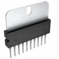
IC DRIVER REV MOTOR 2CH HSIP10
Manufacturer
Rohm Semiconductor
Specifications of BA6238A
Applications
DC Motor Driver
Number Of Outputs
2
Current - Output
1.6A
Voltage - Supply
8 V ~ 18 V
Operating Temperature
-25°C ~ 75°C
Mounting Type
Through Hole
Package / Case
10-SIP + Tab
Lead Free Status / RoHS Status
Lead free / RoHS Compliant
Voltage - Load
-
Available stocks
Company
Part Number
Manufacturer
Quantity
Price

Part Number:
BA6238A
Manufacturer:
ROHM/罗姆
Quantity:
20 000
Company:
Part Number:
BA6238AN
Manufacturer:
AD
Quantity:
9 654


○
BA6246, BA6246N, BA6247FP-Y, BA6239A, BA6238A, BA6238AN
c
www.rohm.com
2009 ROHM Co., Ltd. All rights reserved.
3) Control input conditions
4) Switching of rotating direction (FWD/REV)
c) BA6238A, BA6238AN
The input threshold voltage has a positive temperature coefficient and is expressed by:
The input pin is pulled up at about 15kΩ.
Set input voltage with care not to exceed the maximum input voltage (internal voltage regulator).
When the rotating direction is changed over by the motor rotating condition, switch the direction after the motor is
temporarily brought to the BRAKE condition or OPEN condition. It is recommended to keep the relevant conditions as
follows:
The motor in no drive might be influenced momentarily because the all driver outputs low at the brake.
BA6246, BA6246N, BA6247FP-Y ··· 6V
BA6239A, BA6238A, BA6238AN ··· 5V
The circuit diagram associated with the output high voltage setting VR pin is as per shown on the right.
The output high and low voltages V
V
V
V
(Reference values; V
In addition, the relation of VREF voltage to output voltage is expressed by:
VR < VCC1 - V
VR < VCC2 - ( V
Therefore, when the VREF voltage condition is as follows, the output high voltage is restricted.
VR > VCC1 - V
VR > VCC2 - ( V
V
V
via BRAKE: Longer than braking time*.
ΔVIH
OH
OH
OL
OH
OH
ΔT
via OPEN: The time longer than 1 ms is recommended (BA6246, BA6246N only)
= V
= VR + ( V
≈ VR
= VCC1 - V
= VCC2 - V
SAT(Q7)
= +2.8mV / °C
+ V
(* the time required for the output L terminal to achieve potential below GND when brake is activated.)
F(Q5)
SAT(Q1)
SAT(Q1)
SAT(Q1)
SAT(Q2)
SAT(Q2)
SAT(Q2)
F(Q6)
+ V
SAT
- V
- V
- V
- V
F(Q4)
+ V
+ V
≈ 0.1V, V
F(Q4)
F(Q4)
F(Q2)
F(Q3)
F(Q3)
F(Q3)
) - ( V
- V
- V
- V
ΔVIL
) + (V
) + (V
ΔT
F(Q5)
F(Q5)
F(Q3)
F(Q2)
F
OH
≈ 0.7V)
F(Q2)
F(Q2)
+ V
and V
= +1.6mV / °C
F(Q3)
+ V
+ V
OL
F(Q3)
F(Q3)
)
are expressed by:
) - ( V
) - ( V
12/15
F(Q4)
F(Q4)
+ V
+ V
F(Q5)
F(Q5)
)
)
Fig.37 BA6238A, BA6238AN
VR
Q1
Q4
Q5
Technical Note
2009.04 - Rev.A
Q2
Q7
Q3
Q6
VCC1
VCC2
OUT
GND
Related parts for BA6238A
Image
Part Number
Description
Manufacturer
Datasheet
Request
R

Part Number:
Description:
Manufacturer:
Rohm Semiconductor
Datasheet:
Part Number:
Description:
Manufacturer:
Rohm Semiconductor
Datasheet:
Part Number:
Description:
Manufacturer:
Rohm Semiconductor
Datasheet:
Part Number:
Description:
Manufacturer:
Rohm Semiconductor
Datasheet:
Part Number:
Description:
Manufacturer:
Rohm Semiconductor
Datasheet:
Part Number:
Description:
Manufacturer:
Rohm Semiconductor
Datasheet:
Part Number:
Description:
Manufacturer:
Rohm Semiconductor
Datasheet:
Part Number:
Description:
Manufacturer:
Rohm Semiconductor
Datasheet:
Part Number:
Description:
Manufacturer:
Rohm Semiconductor
Datasheet:
Part Number:
Description:
Manufacturer:
Rohm Semiconductor
Datasheet:
Part Number:
Description:
Manufacturer:
Rohm Semiconductor
Datasheet:
Part Number:
Description:
Manufacturer:
Rohm Semiconductor
Datasheet:

Part Number:
Description:
DIODE SWITCH 80V 25MA SMD5 TR
Manufacturer:
Rohm Semiconductor
Datasheet: