L292 STMicroelectronics, L292 Datasheet
L292
Specifications of L292
Available stocks


Related parts for L292


L292 Summary of contents
Page 1
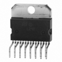
... EXTERNAL LOOP GAIN ADJUSTEMENT SINGLE POWER SUPPLY ( INPUT SIGNAL SYMMETRIC TO GROUND THERMAL PROTECTION DESCRIPTION The L292 is a monolithic LSI circuit in 15-lead Mul- ® tiwatt package intended for use, together with L290 and L291 complete 3-chip motor positioning system for applications such as car- riage/daisy-wheel position control in type-writes ...
Page 2
... L292 PIN CONNECTION (Top view) ABSOLUTE MAXIMUM RATINGS Symbol V Power Supply s V Input Voltage i V Inhibit Voltage inhibit I Output Current o P Total Power Dissipation (T tot T Storage and Junction Temperature stg THERMAL DATA Symbol R Thermal resistance junction-case th-j-case TRUTH TABLE Vinhibit Pin 12 ...
Page 3
... L290/1/2 system follows. At the time, the microprocessor orders a switch to the position mode, (strobe signal at pin 8 of L291) and within the L292 drives the motor to a null position, where it is held by electronic "de-tenting". The mechanical/electrical interface consists of an Figure 1 ...
Page 4
... L292 The system operates in two modes to achieve high speed, high-accurancy positioning. Speed commands for the system originate in the microprocessor continuosly updated on the motor position by means of pulses from the L290 tachometer chip, whitch in tur gets its information from the op- tical encoder. From this basic input, the microprocessor computes a 5-bit control word that sets the system speed dependent on the distance to travel ...
Page 5
... TACHO signal and the risulting error signal is amplified by the error amplifier, and subse- quently appears on pin 1. The ERRV sognal (from pin 1 , L291) is fed to pin 6 of the final chip, the L292 H-bridge motor-driver. This input signals is bidirectional so it must be converted to a positive signal ba- cause the L292 uses a single supply voltage ...
Page 6
... L292 Figure 2. Figure 3. Figure 4. Application Circuit. 6/13 ...
Page 7
... APPLICATION INFORMATION This section has been added in order to help the designer for the best choise of the values of external components. Figure 5. L292 Block Diagram. The schematic diagram used for the Laplace analysis of the system is shown in fig. 6. Figure (sensing resistors ------ - = 2.5 · 10-3 W (current sensing amplifier transconductance) ...
Page 8
... L292 (DC transfer function from the input of the comparator (V ---------- - Neglecting the VCEsat of the bridge transistors and the VBE of the diodes ------- - --------- - where : TRANSFER FUNCTION In order to be sure that the current loop is stable the following condition is imposed : sRC = ------- - (pole cancellation ------- - from which The transfer function is then, ...
Page 9
... R C 0.044 F F -------------- - – S (where V is the amplitude of the input step ------ - 2) = from which 2 0.044 t -------------- - 1 ------------------ - – cos ------------------ - t – ------------------ - i L292 (7) 9/13 ...
Page 10
... V = 1.5 Vp possible to verify that the L292 works in "closed-loop" conditions during the entire motor current rise- time: the voltage at pin 7 inverting input of the error amplifier) is locked to the reference voltage VR, present at the non-inverting input of the same amplifier. The previous linear analysis is correct for this example. ...
Page 11
... and from ( – --------------- - = msec [from expression (2) ] Assuming = from (7) follows : 1 400 ------------------------------- - 0 The cutoff frequency is : – 3 143 kHz = ------------------------- - = Summarising 3 – – 1.10 R sec 1000 C ----------------- - = 1 – – 9 47nF For R = 510 C = 92nF F F L292 11/13 ...
Page 12
... L292 mm DIM. MIN. TYP. MAX. MIN 2. 0.49 0.55 0.019 F 0.66 0.75 0.026 G 1.02 1.27 1.52 0.040 G1 17.53 17.78 18.03 0.690 H1 19.6 0.772 H2 20.2 L 21.9 22.2 22.5 0.862 L1 21.7 22.1 22.5 0.854 L2 17.65 18.1 0.695 L3 17.25 17.5 17.75 0.679 L4 10.3 10 ...
Page 13
... The ST logo is a registered trademark of STMicroelectronics Australia - Brazil - Canada - China - Finland - France - Germany - Hong Kong - India - Israel - Italy - Japan -Malaysia - Malta - Morocco - Singapore - Spain - Sweden - Switzerland - United Kingdom - United States. © 2003 STMicroelectronics - All Rights Reserved STMicroelectronics GROUP OF COMPANIES http://www.st.com L292 13/13 ...