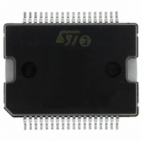
L6258EXTR STMicroelectronics, L6258EXTR Datasheet - Page 13

L6258EXTR
Manufacturer Part Number
L6258EXTR
Description
IC MOTOR DRVR UNIV PWM PWRSO-36
Manufacturer
STMicroelectronics
Type
Driverr
Datasheet
1.E-L6258EXTR.pdf
(32 pages)
Specifications of L6258EXTR
Applications
DC Motor Driver, Stepper Motor Driver
Number Of Outputs
2/1
Current - Output
1.5A
Voltage - Load
12 V ~ 40 V
Voltage - Supply
4.75 V ~ 5.25 V
Mounting Type
Surface Mount
Package / Case
PowerSO-36 Exposed Bottom Pad
Operating Supply Voltage
12 V to 40 V
Mounting Style
SMD/SMT
Operating Temperature
150 C
Lead Free Status / RoHS Status
Lead free / RoHS Compliant
Operating Temperature
-
Lead Free Status / Rohs Status
Lead free / RoHS Compliant
Available stocks
Company
Part Number
Manufacturer
Quantity
Price
Part Number:
L6258EXTR
Manufacturer:
ST
Quantity:
20 000
L6258EX
2.3
2.4
2.5
Table 5.
Phase input ( PH )
The logic level applied to this input determines the direction of the current flowing in the
winding of the motor.
High level on the phase input causes the motor current flowing from OUT_A to OUT_B
through the load.
Triangular generator
This circuit generates the two triangular waves TRI_0 and TRI_180 internally used to
generate the duty cycle variation of the signals driving the output stage in bridge
configuration.
The frequency of the triangular wave defines the switching frequency of the output, and can
be adjusted by changing the capacitor connected at TR1_CAP pin:
where: K = 1.5 x 10
Charge pump circuit
To ensure the correct driving of the high side drivers a voltage higher than Vs is supplied on
the Vboot pin. This boostrap voltage is not needed for the low side power DMOS transistors
because their sources terminals are grounded. To produce this voltage a charge pump
method is used. It is made by using two external capacitors; one connected to the internal
oscillator (CP) and the other (Cboot) to storage the overvoltage needed for the driving the
gates of the high side DMOS. The value suggested for the capacitors are:
Table 6.
Component name
I3
L
L
L
L
L
C
C
boot
P
Current levels (continued)
Charge pump capacitor's values
-5
I2
H
L
L
L
L
Component's function
Storage capacitor
Pump capacitor
I1
H
H
L
L
L
F
ref
=
--- -
C
K
I0
H
H
L
L
L
Value
100
10
Functional description
Current level
% of IMAX
88.9
92.1
95.2
98.4
100
Unit
nF
nF
13/32


