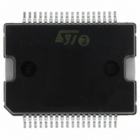
L6258EXTR STMicroelectronics, L6258EXTR Datasheet - Page 15

L6258EXTR
Manufacturer Part Number
L6258EXTR
Description
IC MOTOR DRVR UNIV PWM PWRSO-36
Manufacturer
STMicroelectronics
Type
Driverr
Datasheet
1.E-L6258EXTR.pdf
(32 pages)
Specifications of L6258EXTR
Applications
DC Motor Driver, Stepper Motor Driver
Number Of Outputs
2/1
Current - Output
1.5A
Voltage - Load
12 V ~ 40 V
Voltage - Supply
4.75 V ~ 5.25 V
Mounting Type
Surface Mount
Package / Case
PowerSO-36 Exposed Bottom Pad
Operating Supply Voltage
12 V to 40 V
Mounting Style
SMD/SMT
Operating Temperature
150 C
Lead Free Status / RoHS Status
Lead free / RoHS Compliant
Operating Temperature
-
Lead Free Status / Rohs Status
Lead free / RoHS Compliant
Available stocks
Company
Part Number
Manufacturer
Quantity
Price
Part Number:
L6258EXTR
Manufacturer:
ST
Quantity:
20 000
L6258EX
2.7
With a positive differential voltage on V
positively unbalanced respected Vr.
In this case being the error amplifier output voltage greater than Vr, the output of the first
comparator is a square wave with a duty cycle higher than 50%, while the output of the
second comparator is a square wave with a duty cycle lower than 50%.
The variation in duty cycle obtained at the outputs of the two comparators is the same, but
one is positive and the other is negative with respect to the 50% level.
The two driving signals, generated in this case, drive the two outputs in such a way to have
switched current flowing from OUT_A through the motor winding to OUT_B.
With a negative differential voltage V
unbalanced respected Vr.
In this case the output of the first comparator is a square wave with a duty cycle lower than
50%, while the output of the second comparator is a square wave with a duty cycle higher
than 50%.
The variation in the duty cycle obtained at the outputs of the two comparators is always of
the same.
The two driving signals, generated in this case, drive the the two outputs in order to have the
switched current flowing from OUT_B through the motor winding to OUT_A.
Current control loop compensation
In order to have a flexible system able to drive motors with different electrical characteristics,
the non inverting input and the output of the error amplifier ( EA_OUT ) are available.
Connecting at these pins an external RC compensation network it is possible to adjust the
gain and the bandwidth of the current control loop.
DAC
DAC
, the transconductance loop will be negatively
(see
Figure
5, the transconductance loop will be
Functional description
15/32


