MC33486ADH Freescale Semiconductor, MC33486ADH Datasheet - Page 11
MC33486ADH
Manufacturer Part Number
MC33486ADH
Description
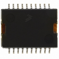
IC SWITCH DUAL H-SIDE 20-HSOP
Manufacturer
Freescale Semiconductor
Datasheet
1.MC33486ADHR2.pdf
(30 pages)
Specifications of MC33486ADH
Applications
DC Motor Controller, H Bridge
Number Of Outputs
1
Current - Output
10A
Voltage - Supply
8 V ~ 28 V
Operating Temperature
-40°C ~ 125°C
Mounting Type
Surface Mount
Package / Case
20-HSOP
Lead Free Status / RoHS Status
Lead free / RoHS Compliant
Voltage - Load
-
Available stocks
Company
Part Number
Manufacturer
Quantity
Price

Part Number:
MC33486ADH
Manufacturer:
FREESCALE
Quantity:
20 000
Part Number:
MC33486ADHR
Manufacturer:
MOTOROLA/摩托罗拉
Quantity:
20 000
Company:
Part Number:
MC33486ADHR2
Manufacturer:
FREESCALE
Quantity:
101


damage (low-side MOSFETs ON). The overtemperature
protection circuitry incorporates hysteresis.
output.
High-Side Overcurrent Protection
35 A typical. When this limit is reached due to an overload
condition or a short to ground, the faulty output is tri-stated.
To clear the fault, the input (INn) line needs to return low, then
on the next high transition the output will be enabled.
Low-Side Block
N-channel power MOSFETs. The low-side control circuitry is
PWM capable and protects the low-side MOSFETs in case of
overcurrent (short to V
the status output.
to protect the gates of the low-side MOSFETs.
page 15, and 14, page 15, depict the characteristics of the
low-side block when a current is sourced from the GLS pin or
sinked from the GLS pin, respectively.
driven by the high side. The low-side gate driver will only turn
on when the voltage (same connection as OUT1 or OUT2) of
the internal high sides is less than 2.0 V, which prevents any
cross-conduction in the bridge.
Low-Side Overcurrent Protection
protection does not measure the current; rather, it measures
the effect of current on the low-side power MOSFETs through
a condition: V
conditions occurs for 3.0 µ s typical (blanking time), both
outputs OUT1 and OUT2 are tri-stated. The full bridge is tri-
stated to prevent the motor running in case of short to V
Once the fault is removed, the input INn of the OUTn that
experienced the fault must be reset in order to recover normal
mode operation.
MOSFETs only if the overcurrent protection condition is not
reached. If the external low-side power MOSFETs are not
used, a 470 pF capacitor in parallel with a 100 k Ω resistor
can be connected at the GLSn pin to prevent the activation of
the low-side MOSFET overcurrent protection.
Analog Integrated Circuit Device Data
Freescale Semiconductor
Overtemperature fault condition is reported on the status
The 33486A incorporates a current shutdown threshold of
This information is reported on the status output.
The low-side block has control circuitry for two external
The low-side gate controls are clamped at 14 V maximum
During normal operation, the outputs OUT1 and OUT2 are
Unlike the high-side overcurrent circuitry, this overcurrent
The 33486A can be used without the external low-side
GS
> 4.3 V and V
BAT
). This information is reported on
DS
> 1.0 V. When this set of
Figures
13,
BAT
.
ground terminal, it is essential that the low-side source is
connected to this same ground in order to prevent false
overcurrent detection due to ground shifts.
Thermal Management
mount package. This package offers high thermal
performances and high current capabilities. It offers
10 terminals on each package side and one additional
connection, which is the package heat sink (called terminal
21). The heatsink acts as the device power VBAT connection.
maximum. The junction-to-ambient thermal resistance is
dependant on the mounting technology and if an additional
heat sink is used. One of the most commonly used mounting
technique consists of using the printed circuit board and the
copper lines as heatsink.
has a total of 10 cm
on the top side and 7.5 cm
ambient of 25 ° C/W can be achieved. This value is split into:
thicker copper metal, higher number of thermal via from top
to bottom side PCB, and the use of additional thermal via
from the circuit board to the module case.
Figure 7. Printed Board Layout Example (not to scale)
As V
The high-side block is assembled into a power surface
The junction-to-case thermal resistance is 2.0 ° C/W
Figure 7
With the above layout, thermal resistance junction-to-
•Junction to case (R
•Case to ambient (R
Lower value can be reached with the help of larger and
top to down-
Bottom-side PCB
33486A
side PCB
Thermal
via from
GS
8.0 cm
and V
is an example of printed circuit board layout. It
FUNCTIONAL INTERNAL BLOCK DESCRIPTION
DS
2
2
are measured in respect to the 33486A
additional copper on two sides (2.5 cm
θJC
θCA
) = 2.0 ° C/W
) = 23 ° C/W
2
External PCB (4 x 4 cm)
on the down side).
FUNCTIONAL DESCRIPTION
Top-side PCB
2.0 cm
2
33486A
11
2
Related parts for MC33486ADH
Image
Part Number
Description
Manufacturer
Datasheet
Request
R


Part Number:
Description:
Manufacturer:
Freescale Semiconductor, Inc
Datasheet:
Part Number:
Description:
Manufacturer:
Freescale Semiconductor, Inc
Datasheet:
Part Number:
Description:
Manufacturer:
Freescale Semiconductor, Inc
Datasheet:
Part Number:
Description:
Manufacturer:
Freescale Semiconductor, Inc
Datasheet:
Part Number:
Description:
Manufacturer:
Freescale Semiconductor, Inc
Datasheet:
Part Number:
Description:
Manufacturer:
Freescale Semiconductor, Inc
Datasheet:
Part Number:
Description:
Manufacturer:
Freescale Semiconductor, Inc
Datasheet:
Part Number:
Description:
Manufacturer:
Freescale Semiconductor, Inc
Datasheet:
Part Number:
Description:
Manufacturer:
Freescale Semiconductor, Inc
Datasheet:
Part Number:
Description:
Manufacturer:
Freescale Semiconductor, Inc
Datasheet:
Part Number:
Description:
Manufacturer:
Freescale Semiconductor, Inc
Datasheet:
Part Number:
Description:
Manufacturer:
Freescale Semiconductor, Inc
Datasheet:
Part Number:
Description:
Manufacturer:
Freescale Semiconductor, Inc
Datasheet:
Part Number:
Description:
Manufacturer:
Freescale Semiconductor, Inc
Datasheet: