MC33486ADH Freescale Semiconductor, MC33486ADH Datasheet - Page 12
MC33486ADH
Manufacturer Part Number
MC33486ADH
Description
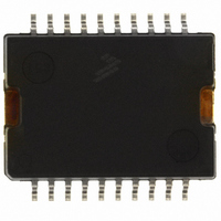
IC SWITCH DUAL H-SIDE 20-HSOP
Manufacturer
Freescale Semiconductor
Datasheet
1.MC33486ADHR2.pdf
(30 pages)
Specifications of MC33486ADH
Applications
DC Motor Controller, H Bridge
Number Of Outputs
1
Current - Output
10A
Voltage - Supply
8 V ~ 28 V
Operating Temperature
-40°C ~ 125°C
Mounting Type
Surface Mount
Package / Case
20-HSOP
Lead Free Status / RoHS Status
Lead free / RoHS Compliant
Voltage - Load
-
Available stocks
Company
Part Number
Manufacturer
Quantity
Price

Part Number:
MC33486ADH
Manufacturer:
FREESCALE
Quantity:
20 000
Part Number:
MC33486ADHR
Manufacturer:
MOTOROLA/摩托罗拉
Quantity:
20 000
Company:
Part Number:
MC33486ADHR2
Manufacturer:
FREESCALE
Quantity:
101


Thermal Model
mounted on a printed circuit board can be spit into two main
parts: junction-to-case and case-to-ambient resistances.
The use of this model is similar to the electrical Ohm law
(voltage = resistance x current), where:
12
33486A
FUNCTIONAL DESCRIPTION
FUNCTIONAL INTERNAL BLOCK DESCRIPTION
(1.0 A = 1.0 W of
Power Dissipation)
The junction-to-ambient thermal resistance of the circuit
Figure 8
•Voltage represents temperature.
•Current represents power dissipated by the device.
•Resistance represents thermal resistance.
We finally have:
Temperature or delta temperature = power dissipation
times thermal resistance; that is, ° C = W x °C/W.
Power (W)
shows a simplified steady state model.
Figure 8. Simplified Thermal Model
(Electrical Equivalent)
R
θJC
Switch
(1.0 Ω = 1.0°C/W)
Ambient Temperature Node
(1.0 V = 1.0°C Ambient Temperature)
Case Temperature Node
Junction Temperature Node
Surface Temperature)
(Volts represent Die
R
θCA
the amount of power flowing through the thermal resistances.
Example
temperature is 85 ° C + 55 ° C = 140 ° C.
ambient thermal resistance, assuming that ambient
temperature is 85 ° C.
are located inside a module, the ambient temperature of the
module should be taken into account. Or an additional
thermal resistance from inside module to external ambient
temperature must be added. The calculation method remains
the same.
package. Junction-to-case thermal resistance is
approximately 2/0 ° C/W. The junction-to-ambient thermal
resistance follows the same rules as for the high-side block
and is in the same range.
1. Numerical Value
2. Results
Any node temperature can easily be calculated knowing
Assuming an 85 ° C ambient temperature, the junction
The above example takes into account the junction-to-
In the case where the device plus its printed circuit board
The low-side block is packaged into D
•Junction-to-case thermal resistance (R
•Power into the switch: Assuming the device is driving
•Case-to-ambient thermal resistance (R
•Junction-to-case delta temperature: 5.0 ° C (2.5 W x
•Case delta temperature from ambient: 50 ° C (20 ° C/W x
•Actual junction temperature node will be:
8.0 A at 150 ° C junction temperature (R
150 ° C is 40 m Ω ), the total power dissipation is 0.04 *
8 * 8 = 2.56 W
2.0 ° C/W)
2.5 W)
50 ° C + 5.0 ° C = 55 ° C above the ambient
temperature.
Analog Integrated Circuit Device Data
Freescale Semiconductor
2
PAK or DPAK
θJC
θCA
DS(ON)
): 2.0 ° C/W
): 20 ° C/W
at
Related parts for MC33486ADH
Image
Part Number
Description
Manufacturer
Datasheet
Request
R


Part Number:
Description:
Manufacturer:
Freescale Semiconductor, Inc
Datasheet:
Part Number:
Description:
Manufacturer:
Freescale Semiconductor, Inc
Datasheet:
Part Number:
Description:
Manufacturer:
Freescale Semiconductor, Inc
Datasheet:
Part Number:
Description:
Manufacturer:
Freescale Semiconductor, Inc
Datasheet:
Part Number:
Description:
Manufacturer:
Freescale Semiconductor, Inc
Datasheet:
Part Number:
Description:
Manufacturer:
Freescale Semiconductor, Inc
Datasheet:
Part Number:
Description:
Manufacturer:
Freescale Semiconductor, Inc
Datasheet:
Part Number:
Description:
Manufacturer:
Freescale Semiconductor, Inc
Datasheet:
Part Number:
Description:
Manufacturer:
Freescale Semiconductor, Inc
Datasheet:
Part Number:
Description:
Manufacturer:
Freescale Semiconductor, Inc
Datasheet:
Part Number:
Description:
Manufacturer:
Freescale Semiconductor, Inc
Datasheet:
Part Number:
Description:
Manufacturer:
Freescale Semiconductor, Inc
Datasheet:
Part Number:
Description:
Manufacturer:
Freescale Semiconductor, Inc
Datasheet:
Part Number:
Description:
Manufacturer:
Freescale Semiconductor, Inc
Datasheet: