MC33486ADH Freescale Semiconductor, MC33486ADH Datasheet - Page 9
MC33486ADH
Manufacturer Part Number
MC33486ADH
Description
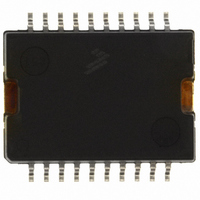
IC SWITCH DUAL H-SIDE 20-HSOP
Manufacturer
Freescale Semiconductor
Datasheet
1.MC33486ADHR2.pdf
(30 pages)
Specifications of MC33486ADH
Applications
DC Motor Controller, H Bridge
Number Of Outputs
1
Current - Output
10A
Voltage - Supply
8 V ~ 28 V
Operating Temperature
-40°C ~ 125°C
Mounting Type
Surface Mount
Package / Case
20-HSOP
Lead Free Status / RoHS Status
Lead free / RoHS Compliant
Voltage - Load
-
Available stocks
Company
Part Number
Manufacturer
Quantity
Price

Part Number:
MC33486ADH
Manufacturer:
FREESCALE
Quantity:
20 000
Part Number:
MC33486ADHR
Manufacturer:
MOTOROLA/摩托罗拉
Quantity:
20 000
Company:
Part Number:
MC33486ADHR2
Manufacturer:
FREESCALE
Quantity:
101


and two low-side MOSFETS. Each block has a dedicated
package.
power MOSFETS and two low-side gate drivers. The outputs
are fully protected against shorts to ground, shorts to V
SUPPLY VOLTAGE (V
supply of the device. It has undervoltage and overvoltage
detection. In addition to its supply function, the tab
contributes to the thermal behavior of the device by
conducting the heat from the switching MOSFET to the
printed circuit board.
INPUTS (IN1 AND IN2)
control the outputs (OUT1 and OUT2) and the gates of the
low-side power MOSFETs (GLS1 and GLS2). When the input
is a logic LOW, the associated output is low (high-side
internal MOSFETs OFF and low-side external MOSFETs
ON). (Refer to
information.) These terminals are 5.0 V CMOS-compatible
inputs.
OUTPUTS (OUT1 AND OUT2)
high-side MOSFETs. OUT1 and OUT2 are controlled using
the
current limited and thermally protected.
GATE LOW SIDE (GLS1 AND GLS2)
low-side MOSFETs. These MOSFETs are controlled using
IN1 and IN2 inputs. When the input (INn) is logic HIGH, the
associated GLS is grounded to turn off the external low-side
MOSFET. (Refer to
information.)
Power Supply
line. The device has a standby mode (Wake at low logic level)
with a ultra-low consumption (10 µ A max). In operation when
inputs are active, the supply current is up to 20 mA.
Analog Integrated Circuit Device Data
Freescale Semiconductor
The full bridge is partitioned into three blocks, the 33486A
The 33486A incorporates two 15 m Ω N-channel high-side
The backside of the 33486A, called the tab, is the power
IN1 and IN2 terminals are input control terminals used to
OUT1 and OUT2 terminals are the sources of the internal
GLS1 and GLS2 terminals are the gates of the external
The 33486A can be directly connected to the power supply
IN1 and IN2 inputs,
Table 5, TRUTH
Table 5, TRUTH TABLE
respectively
BAT
)
TABLE, page 21, for more
FUNCTIONAL INTERNAL BLOCK DESCRIPTION
.
These outputs are
FUNCTIONAL TERMINAL DESCRIPTION
FUNCTIONAL DESCRIPTION
for more
INTRODUCTION
BAT
,
shorted loads, overvoltage / undervoltage, and
overtemperature. The device can directly interface with a
microcontroller for control and diagnostic functions.
H-Bridge configuration.
WAKE
mode. When WAKE terminal voltage is a logic LOW state, the
device is in sleep mode and its bias current is at a minimum.
The device is enabled and fully operational when WAKE
terminal voltage is logic HIGH.
STATUS (ST)
mode. It reports overtemperature and / or overcurrent faults. It
goes active low when a fault mode is detected by the device
on either one channel or both simultaneously. Its internal
structure is an open-drain architecture with an internal clamp
at 6.0 V. An external 10 k Ω pull-up resistor connected to V
(5.0 V) is needed. Refer to
CURRENT SENSE (CUR R)
3700) of the sum of the high-side currents that can be used
to generate signal ground-referenced output voltages for use
by the microcontroller with a 1.0 k Ω pull-down resistor.
GROUND (GND)
33486A, it is recommended that sufficient capacitance (tens
of microfarads) be placed between VBAT and GND of the IC.
This will help ensure that the power supply stays within the
specified limits.
high logic level. It is self-oscillating with a frequency that can
The 33486A is designed for typical DC-motor control in an
The WAKE terminal is used to place the device in a sleep
The status terminal indicates when the device is in fault
The Current Sense terminal delivers a ratio amount (1/
This terminal is the ground of the device.
With the high current and fast switching ability of the
The internal charge pump is activated when Wake is at
Table 5, TRUTH TABLE.
FUNCTIONAL DESCRIPTION
INTRODUCTION
33486A
DD
9
Related parts for MC33486ADH
Image
Part Number
Description
Manufacturer
Datasheet
Request
R


Part Number:
Description:
Manufacturer:
Freescale Semiconductor, Inc
Datasheet:
Part Number:
Description:
Manufacturer:
Freescale Semiconductor, Inc
Datasheet:
Part Number:
Description:
Manufacturer:
Freescale Semiconductor, Inc
Datasheet:
Part Number:
Description:
Manufacturer:
Freescale Semiconductor, Inc
Datasheet:
Part Number:
Description:
Manufacturer:
Freescale Semiconductor, Inc
Datasheet:
Part Number:
Description:
Manufacturer:
Freescale Semiconductor, Inc
Datasheet:
Part Number:
Description:
Manufacturer:
Freescale Semiconductor, Inc
Datasheet:
Part Number:
Description:
Manufacturer:
Freescale Semiconductor, Inc
Datasheet:
Part Number:
Description:
Manufacturer:
Freescale Semiconductor, Inc
Datasheet:
Part Number:
Description:
Manufacturer:
Freescale Semiconductor, Inc
Datasheet:
Part Number:
Description:
Manufacturer:
Freescale Semiconductor, Inc
Datasheet:
Part Number:
Description:
Manufacturer:
Freescale Semiconductor, Inc
Datasheet:
Part Number:
Description:
Manufacturer:
Freescale Semiconductor, Inc
Datasheet:
Part Number:
Description:
Manufacturer:
Freescale Semiconductor, Inc
Datasheet: