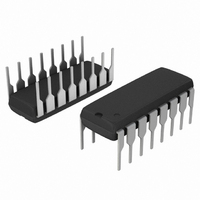
MC33030PG ON Semiconductor, MC33030PG Datasheet - Page 9

MC33030PG
Manufacturer Part Number
MC33030PG
Description
IC CTLR MOTOR DC SERVO 16DIP
Manufacturer
ON Semiconductor
Type
DC Motor Driverr
Datasheet
1.MC33030P.pdf
(17 pages)
Specifications of MC33030PG
Applications
DC Motor Controller, Servo
Number Of Outputs
1
Current - Output
1A
Voltage - Supply
8 V ~ 36 V
Operating Temperature
-40°C ~ 85°C
Mounting Type
Through Hole
Package / Case
16-DIP (0.300", 7.62mm)
Operating Current
25mA
Operating Temperature Classification
Industrial
Motor Controller Type
DC Motor Driver
Package Type
PDIP
Operating Supply Voltage (min)
8V
Operating Supply Voltage (max)
36V
Supply Current
25 mA
Mounting Style
Through Hole
Lead Free Status / RoHS Status
Lead free / RoHS Compliant
Voltage - Load
-
Lead Free Status / Rohs Status
Compliant
Other names
MC33030PGOS
Output Filter/
try to follow and center about the reference voltage setting
if it is within the input common−mode voltage range of
Pin 3; Figures 4 and 5. Initially consider that the feedback
input voltage level is somewhere on the dashed line between
V
defined above and the motor will be off. Now if the reference
voltage is raised so that V
will turn−on [3] enabling Q Drive, causing Drive Output A
to sink and B to source motor current [8]. The actuator will
move in Direction B until V
Comparator B will turn−off, activating the brake enable [4]
V
Error Amp
Input Filter
Feedback
Reference
V
CC
2
CC
It must be remembered that points V
Inverting
Output
and V
Input
Reference
Input
Input
Inverting
Non−
Input
4
in [1]. This is within the dead zone range as
8 20 k Error Amp
7
6
3
1
2
20 k
100 k
100 k
20 k
Detector
Window
+
mA
9
3.0 k
3.0 k
35
mA
35
20 k
Figure 17. Representative Block Diagram and Typical Servo Application
+
Input
Filter
Pin 3
Pin 3
0.3 mA
is less than V
becomes greater than V
B
A
4, 5,12,13
GND
1
through V
Gearbox and Linkage
4
, comparator B
18 V
Ref.
Current
4
Over−
Latch
Drive Brake Logic
Overvoltage
always
http://onsemi.com
Monitor
Direction
MC33030
Q
Q
1
Latch
Brake Enable
.
Q Drive
R
S
9
R
S
Q Drive
7.5 V
Overcurrent
Ref.
and Q Brake [6] causing Drive Output A to go high and B to
go into a high impedance state. The inertia of the mechanical
system will drive the motor as a generator creating a positive
voltage on Pin 10 with respect to Pin 14. The servo system
can be stopped quickly, so as not to over−shoot through the
dead zone range, by braking. This is accomplished by
shorting the motor/generator terminals together. Brake
current will flow into the diode at Drive Output B, through
the internal V
transistor at Drive Output A. The end of the solid line and
beginning of the dashed for V
resting position of the actuator after braking.
Q
Q
Delay
Q Brake
5.5
mA
Q Brake
C
50 k
16
DLY
CC
V
CC
11
rail, and out the emitter of the sourcing
Output B
Drive
+
R
15
OC
Pin 3
10
H−Switch
Power
Overcurrent
Reference
Motor
[1] indicates the possible
Drive
Output A
14
Overcurrent
Monitor
+


