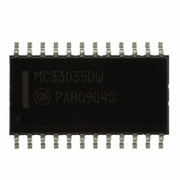
MC33035DWR2G ON Semiconductor, MC33035DWR2G Datasheet - Page 17

MC33035DWR2G
Manufacturer Part Number
MC33035DWR2G
Description
IC CTRLR MOTOR DC BRSHLSS 24SOIC
Manufacturer
ON Semiconductor
Type
Brushless DC Motor Controllerr
Datasheet
1.NCV33035DWR2G.pdf
(28 pages)
Specifications of MC33035DWR2G
Applications
DC Motor Controller, Brushless (BLDC)
Number Of Outputs
1
Current - Output
100mA
Voltage - Load
5.9 V ~ 6.5 V
Voltage - Supply
10 V ~ 30 V
Operating Temperature
-40°C ~ 85°C
Mounting Type
Surface Mount
Package / Case
24-SOIC (7.5mm Width)
Operating Supply Voltage
10 V to 30 V
Supply Current
20 mA
Mounting Style
SMD/SMT
Operating Current
20mA
Operating Temperature Classification
Industrial
Package Type
SOIC
Operating Supply Voltage (min)
10V
Operating Supply Voltage (max)
30V
Lead Free Status / RoHS Status
Lead free / RoHS Compliant
Other names
MC33035DWR2GOS
MC33035DWR2GOS
MC33035DWR2GOSTR
MC33035DWR2GOS
MC33035DWR2GOSTR
Available stocks
Company
Part Number
Manufacturer
Quantity
Price
Company:
Part Number:
MC33035DWR2G
Manufacturer:
FREESCALE
Quantity:
1 500
Part Number:
MC33035DWR2G
Manufacturer:
ON/安森美
Quantity:
20 000
Three Phase Motor Commutation
full−featured open loop motor controller with full wave, six
step drive. The upper power switch transistors are
Darlingtons while the lower devices are power MOSFETs.
Each of these devices contains an internal parasitic catch
diode that is used to return the stator inductive energy back
to the power supply. The outputs are capable of driving a
delta or wye connected stator, and a grounded neutral wye
if split supplies are used. At any given rotor position, only
one top and one bottom power switch (of different totem
poles) is enabled. This configuration switches both ends of
the stator winding from supply to ground which causes the
current flow to be bidirectional or full wave. A leading edge
spike is usually present on the current waveform and can
cause a current−limit instability. The spike can be eliminated
by adding an RC filter in series with the Current Sense Input.
Using a low inductance type resistor for R
The three phase application shown in Figure 36 is a
R
C
T
Fwd/Rev
60°/120°
T
Enable
V
Speed
Set
M
Faster
22
17
18
11
12
13
10
4
5
6
3
7
8
Error Amp
Reference
Regulator
Oscillator
25 μA
Figure 36. Three Phase, Six Step, Full Wave Motor Controller
PWM
Undervoltage
Lockout
Shutdown
Thermal
S
Gnd
Decoder
Position
will also aid in
R
S
S
R
Rotor
SYSTEM APPLICATIONS
Q
Q
16
MC33035, NCV33035
http://onsemi.com
17
spike reduction. Care must be taken in the selection of the
bottom power switch transistors so that the current during
braking does not exceed the device rating. During braking,
the peak current generated is limited only by the series
resistance of the conducting bottom switch and winding.
If the motor is running at maximum speed with no load, the
generated back EMF can be as high as the supply voltage,
and at the onset of braking, the peak current may approach
twice the motor stall current. Figure 37 shows the
commutation waveforms over two electrical cycles. The
first cycle (0° to 360°) depicts motor operation at full speed
while the second cycle (360° to 720°) shows a reduced speed
with about 50% pulse width modulation. The current
waveforms reflect a constant torque load and are shown
synchronous to the commutation frequency for clarity.
Brake
23
I
Limit
I
peak
14
2
1
24
21
20
19
9
15
+
C
R
Fault
Ind.
switch
V
Q
Q
3
M
6
R
V
) R
) EMF
M
Q
Q
2
5
winding
Q
1
Q
R
4
S
A
B
C
S
Motor
N
N
S


