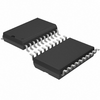
LT1509ISW#PBF Linear Technology, LT1509ISW#PBF Datasheet - Page 11

LT1509ISW#PBF
Manufacturer Part Number
LT1509ISW#PBF
Description
IC PFC CTRLR AVERAGE CURR 20SOIC
Manufacturer
Linear Technology
Datasheet
1.LT1509CN.pdf
(16 pages)
Specifications of LT1509ISW#PBF
Mode
Average Current
Frequency - Switching
100kHz
Voltage - Supply
27V
Operating Temperature
-40°C ~ 125°C
Mounting Type
Surface Mount
Package / Case
20-SOIC (7.5mm Width)
Lead Free Status / RoHS Status
Lead free / RoHS Compliant
Current - Startup
-
Lead Free Status / Rohs Status
Compliant
Available stocks
Company
Part Number
Manufacturer
Quantity
Price
APPLICATIONS
input up to V
V
pull SS2 low disabling the PWM section if the PFC output
voltage falls below approximately 62% of its preset value
(240V with nominal 382V output).
Start Up and Supply Voltage
The LT1509 draws only 250 A before the chip starts at
16V on V
line to V
while switching starts (see Figure 8); then the auxiliary
winding takes over and supplies the operating current.
Note that D3 and the larger values of C3 are only necessary
for systems that have sudden large load variations down
to minimum load and/or very light load conditions. Under
these conditions the loop may exhibit a start/restart mode
because switching remains off long enough for C4 to
discharge below 10V. Large values for C3 will hold V
until switching resumes. For less severe load variations D3
is replaced with a short and C3 is omitted. The turns ratio
between the primary winding determines V
according to :
for 382V V
C
LINE
. The PWMOK comparator contains hysteresis and will
V
CC
V
OUT
– 2V
CC
CC
OUT
MAIN INDUCTOR
. To trickle start, a 91k resistor from the power
supplies trickle current, and C4 holds V
D2
C
=
and then the SS2 voltage continues beyond
and 18V V
D1
N
N
P
S
U
N
N
P
S
INFORMATION
Figure 8
CC
U
+
+
, Np/Ns 19.
C1
2 F
C2
2 F
91k
1W
R1
W
+
C3
390 F
D3
+
U
LT1509 • F08
C4
100 F
CC
CC
V
up
up
CC
CC
Output Capacitor (PFC Section)
GTDR2 (PWM) pulse is synchronized to GTDR1 (PFC) pulse
with 53% duty cycle delay to reduce RMS ripple current in the
output capacitor. See PFC/PWM Synchronization graph in
the Typical Performance Characteristics section.
The peak-to-peak 120Hz PFC output ripple is determined by:
where I
and Z is the capacitor impedance at 120Hz.
For 470 F, impedance is 2.8 at 120Hz. At 335W load,
I
5V. If less ripple is desired higher capacitance should be
used. The selection of the output capacitor is based on
voltage ripple, hold-up time and ripple current. Assuming
the DC converter (PWM section) is designed to operate
with 240V to 382V
function of the energy storage capacity of the capacitor:
with C
t
current can be divided into two major components. The
first is the 120Hz component which is related to the DC
load current as follows:
The second component is made up of switching frequency
components due to the PFC stage charging the capacitor
and the PWM stage discharging the capacitor. For a 300W
output PFC forward converter running from an input
voltage of 100V
was measured to be 1.79A
For the United Chemicon KMH 450V capacitor series,
ripple current at 100kHz is specified 1.43 times higher
than the 120Hz limit.
LOAD(DC)
HOLD
I
V
t
120HZ
HOLD
P-P
= 60ms which is 3.6 line cycles at 60Hz. The ripple
OUT
LOAD(DC)
= 2I
=
= 335V/382V = 0.88A, V
= 470 F, V
(0.5)C
I
LOAD(DC)
LOAD(DC)
P
RMS
OUT
is the DC load current of the PWM stage
OUT
, the total high frequency ripple current
IN
(Z)
, the minimum hold-up time is a
P-P
2
(382V – 0.5V
RMS
= 11.5V, and P
.
P-P
= (2)(0.88)(2.8 ) =
P–P
)
OUT
2
LT1509
– 240V
= 335W,
11
2


