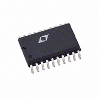
LT1508ISW Linear Technology, LT1508ISW Datasheet

LT1508ISW
Specifications of LT1508ISW
Related parts for LT1508ISW
LT1508ISW Summary of contents
Page 1
... PWM soft start begins when the PFC output reaches the preset voltage. In the event of brief line loss, PWM will be shut off when the PFC output voltage drops below 73% of the preset value. , LTC and LT are registered trademarks of Linear Technology Corporation ...
Page 2
... OUT SENSE OUT U W INFORMATION ORDER PART TOP VIEW NUMBER 20 GTDR2 19 I LIM LT1508CN LT1508CSW LT1508IN 16 SS1 LT1508ISW 15 R SET 14 V SENSE 13 SS2 12 V REF 11 OVP SW PACKAGE 20-LEAD PLASTIC SO WIDE = 125 C, = 100 125 C, = 120 C/ W (SW 100 0V SENSE OUT MIN TYP MAX 0 ...
Page 3
ELECTRICAL C HARA TERISTICS C Maximum operating voltage ( 25V, V MAX VA = 5V, OVP = load on any outputs unless otherwise noted. OUT REF PARAMETER Current Amplifier (PFC Section) Current Amp Offset Voltage ...
Page 4
LT1508 ELECTRICAL C HARA TERISTICS 18V 15k to GND 1nF to GND SET SET outputs, unless otherwise noted. PARAMETER Soft Start Current SS1 Current (PFC) SS2 Current (PWM) Comparators in PWM ...
Page 5
W U TYPICAL PERFORMANCE CHARACTERISTICS Reference Voltage vs Temperature 7.536 7.524 7.512 7.500 7.488 7.476 7.464 7.452 7.440 7.428 –75 –50 – JUNCTION TEMPERATURE ( C) Supply Current vs Supply Voltage –55 C ...
Page 6
LT1508 W U TYPICAL PERFORMANCE CHARACTERISTICS R Voltage vs Current SET 120 100 –20 –40 –60 –80 –100 0 –0.2 –0.4 –0.6 R CURRENT (mA) SET PIN FUNCTIONS (For application help with ...
Page 7
PIN FUNCTIONS (For application help with the PFC portion of this chip, see the LT1248 data sheet) R (Pin 15): A resistor from R SET oscillator charging current and the maximum multiplier output current which is used ...
Page 8
LT1508 APPLICATIONS INFORMATION 0.15 – REF 20k OUT SENSE R IAC Figure 2 ...
Page 9
U U APPLICATIONS INFORMATION (P )(R )(25)( OUT )(R See Figure 2 for R . REF VA is squared in the multiplier, resulting in excellent OUT performance over a wide range ...
Page 10
LT1508 U U APPLICATIONS INFORMATION line current reaches the secondary limit, the comparator takes over control and hysteresis may occur causing audible noise. Overvoltage Protection (PFC Section) Because of the slow loop response necessary for power factor correction, output overshoot ...
Page 11
U U APPLICATIONS INFORMATION input and then the SS2 voltage continues beyond The PWMOK comparator contains hysteresis and will C pull SS2 low disabling the PWM section if the PFC output voltage falls below ...
Page 12
LT1508 U U APPLICATIONS INFORMATION The total equivalent 120Hz ripple in the output capacitor can be calculated by RMS 120HZ 1. 100kHz Ripple Current. HF For I = 0.88A, 1 ...
Page 13
U U APPLICATIONS INFORMATION W U LT1508 13 ...
Page 14
LT1508 U U APPLICATIONS INFORMATION An LT1431 reference/amplifier coupled to a low cost optoisolator closes the loop from secondary side to pri- mary side. Efficiency versus power and line voltage is shown in Figure 10. The PFC preregulator alone has ...
Page 15
... MOLD FLASH OR PROTRUSIONS SHALL NOT EXCEED 0.010 INCH (0.254mm) Information furnished by Linear Technology Corporation is believed to be accurate and reliable. However, no responsibility is assumed for its use. Linear Technology Corporation makes no represen- tation that the interconnection of its circuits as described herein will not infringe on existing patent rights. ...
Page 16
... Simplified PFC Design Current Mode PWM 0.496 – 0.512* (12.598 – 13.005 0.394 – 0.419 (10.007 – 10.643 0.037 – 0.045 (0.940 – 1.143) 0.004 – 0.012 (0.102 – 0.305) S20 (WIDE) 0396 1508f LT/TP 0697 7K • PRINTED IN USA LINEAR TECHNOLOGY CORPORATION 1995 ...


