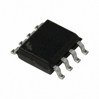
FAN4803CS1 Fairchild Semiconductor, FAN4803CS1 Datasheet

FAN4803CS1
Specifications of FAN4803CS1
FAN4803CS1_NL
Related parts for FAN4803CS1
FAN4803CS1 Summary of contents
Page 1
FAN4803 8-Pin PFC and PWM Controller Combo Features • Internally synchronized PFC and PWM in one 8-pin IC • Patented one-pin voltage error amplifier with advanced input current shaping technique • Peak or average current, continuous boost, leading edge PFC ...
Page 2
FAN4803 Pin Configuration Pin Description Pin Name 1 PFC OUT PFC driver output 2 GND Ground 3 I Current sense input to the PFC current limit comparator SENSE 4 VEAO PFC one-pin error amplifier input 5 V PWM voltage feedback ...
Page 3
PRODUCT SPECIFICATION Electrical Characteristics Unless otherwise specified 15V Symbol Parameter One-pin Error Amplifier V Output Current EAO Line Regulation V OVP Comparator CC Threshold Voltage PFC I Comparator LIMIT Threshold Voltage Delay to Output DC I ...
Page 4
FAN4803 Functional Description The FAN4803 consists of an average current mode boost Power Factor Corrector (PFC) front end followed by a syn- chronized Pulse Width Modulation (PWM) controller distinguished from earlier combo controllers by its low pin count, ...
Page 5
PRODUCT SPECIFICATION GND GND is the return point for all circuits associated with this part. Note: a high-quality, low impedance ground is critical to the proper operation of the IC. High frequency grounding techniques should be used. Power Factor Correction ...
Page 6
FAN4803 In the case of leading edge modulation, the switch is turned OFF right at the leading edge of the system clock. When the modulating ramp reaches the level of the error amplifier output voltage, the switch will be turned ...
Page 7
PRODUCT SPECIFICATION COMP COMP 330 k COMP ZERO COMP 016 . ZERO ...
Page 8
FAN4803 Subsequently the PFC gate drive is initiated, eliminating the necessary dead time needed for the DCM mode. This forces the output to run away until the V OVP shuts down the CC PFC. This situation is corrected by adding ...
Page 9
PRODUCT SPECIFICATION V OVP assumed voltage proportional to the PFC CC output voltage, typically a bootstrap winding off the boost inductor. The V OVP comparator senses when this volt- CC age exceeds 16V, and ...
Page 10
FAN4803 C19 4.7nF 250VAC LINE F1 5A 250V GBU4J C4 J1-1 R24 0.47 F BR1 470k 250VAC 600V 0.5W 4A NEUTRAL J1-2 C20 4.7nF 250VAC R3 0.15 3W R30 200 C29 0. 0.1 ...
Page 11
PRODUCT SPECIFICATION Mechanical Dimensions 0.189 - 0. 0.017 - 0.027 (0.43 - 0.69) (4 PLACE S ) 0.012 - 0.020 0.055 - 0.061 (0.30 - 0.51) (1.40 - 1.55) 0.020 MIN (0.51 MIN) (4 PLACES) 0.170 MAX (4.32 ...
Page 12
... NEITHER DOES IT CONVEY ANY LICENSE UNDER ITS PATENT RIGHTS, NOR THE RIGHTS OF OTHERS. LIFE SUPPORT POLICY FAIRCHILD’S PRODUCTS ARE NOT AUTHORIZED FOR USE AS CRITICAL COMPONENTS IN LIFE SUPPORT DEVICES OR SYSTEMS WITHOUT THE EXPRESS WRITTEN APPROVAL OF THE PRESIDENT OF FAIRCHILD SEMICONDUCTOR CORPORATION. As used herein: 1. Life support devices or systems are devices or systems ...


