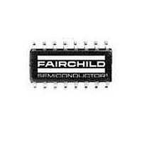
SG6903SZ Fairchild Semiconductor, SG6903SZ Datasheet - Page 3

SG6903SZ
Manufacturer Part Number
SG6903SZ
Description
IC PFC CONTROLLER 16SOIC
Manufacturer
Fairchild Semiconductor
Datasheet
1.SG6903SZ.pdf
(19 pages)
Specifications of SG6903SZ
Mounting Type
Surface Mount
Package / Case
16-SOIC (3.9mm Width)
Output Voltage
1.5 V to 8 V
Switching Frequency
65 KHz
Operating Temperature Range
- 20 C to + 85 C
Mounting Style
SMD/SMT
Duty Cycle (max)
83 %
Lead Free Status / RoHS Status
Lead free / RoHS Compliant
Voltage - Supply
-
Operating Temperature
-
Frequency - Switching
-
Mode
-
Current - Startup
-
Lead Free Status / Rohs Status
Lead free / RoHS Compliant
Green Mode PFC/Flyback-PWM Controller
PIN DESCRIPTIONS
© System General Corp.
Version 1.0.1 (IAO33.0061.B0)
Name
VRMS
RI
IEA
IPFC
IMP
ISENSE
FBPWM
IPWM
OPWM
GND
OPFC
VDD
RANGE
FBPFC
VEA
IAC
Pin No.
1
2
3
4
5
6
7
8
9
10
11
12
13
14
15
16
Type
Line-Voltage
Detection
Oscillator Setting
Output for PFC
Current Amplifier
Inverting Input for
PFC Current Amplifier
Non-inverting Input for
PFC Current Amplifier
Peak Current Limit
Setting for PFC
PWM Feedback Input
PWM Current Sense
PWM Gate Drive
Ground
PFC Gate Drive
Supply
PFC Output-voltage
Control
Voltage Feedback
Input for PFC
Error-Amp Output for
PFC voltage feedback
loop
Input AC Current
Function
Line voltage detection. The pin is used for PFC multiplier, RANGE control of PFC output
voltage, brownout protection. For brownout protection, the controller will be disabled after
a delay time when the VRMS voltage drops below a threshold.
Reference setting. One resistor connected between RI and ground determines the
switching frequency. The switching frequency is equal to [1560 / RI] KHz, where RI is in
KΩ. For example, if RI is equal to 24KΩ, then the switching frequency will be 65 KHz.
This is the output of the PFC current amplifier. The signal from this pin will be compared
with an internal saw-tooth and hence determine the pulse width for PFC gate drive.
The inverting input of the PFC current amplifier. Proper external compensation circuits will
result in excellent input power factor via average-current-mode control.
The non-inverting input of the PFC current amplifier and also the output of multiplier.
Proper external compensation circuits will result in excellent input power factor via
average-current-mode control.
The peak current setting for PFC.
The control input for voltage-loop feedback of PWM stage. It is internally pulled high
through a 6.5 KΩ resistance. Usually an external opto-coupler from secondary feedback
circuit is connected to this pin.
The current sense input for the Flyback PWM. Via a current sense resistor, this pin
provides the control input for peak-current-mode control and cycle by cycle current
limiting.
The totem-pole output drive for the Flyback PWM MOSFET. This pin is internally clamped
under 17V to protect the
Ground
The totem-pole output drive for the PFC MOSFET. This pin is internally clamped under
17V to protect the
The power supply pin.
Two-level output-voltage setting for PFC. The PFC output voltage at low line can be
reduced to improve efficiency. The RANGE pin has high impedance whenever the VRMS
voltage is lower than a threshold.
The feedback input for PFC voltage loop. The inverting input of PFC error amp. This pin is
connected to the PFC output through a divider network.
The error-amp output for PFC voltage feedback loop. A compensation network (usually a
capacitor) is connected between this pin and ground. A large capacitor value will result in
a narrow bandwidth and hence improve the power factor.
Before start-up, this input is used to provide startup current for VDD. For normal operation,
this input is used to provide current reference for the multiplier.
MOSFET.
- 3 -
MOSFET.
www.sg.com.tw • www.fairchildsemi.com
Product Specification
September 28, 2007
SG6903


