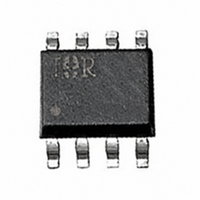
IR1150STR International Rectifier, IR1150STR Datasheet

IR1150STR
Specifications of IR1150STR
IR1150SCT
Available stocks
Related parts for IR1150STR
IR1150STR Summary of contents
Page 1
Features • PFC with IR proprietary “One Cycle Control” • Continuous conduction mode (CCM) boost type PFC • No line voltage sense required • Programmable switching frequency (50kHz-200kHz) • Programmable output overvoltage protection • Brownout and output undervoltage protection • ...
Page 2
Absolute Maximum Ratings Absolute maximum ratings indicate sustained limits beyond which damage to the device may occur. All voltages are absolute voltages referenced to COM. Thermal resistance and power dissipation are measured under board mounted and still air conditions. Parameters ...
Page 3
Electrical Characteristics cont. The electrical characteristics involve the spread of values guaranteed within the specified supply voltage and junction temperature range T from – 25°C to 125°C. Typical values represent the median values, which are related to 25°C. If not ...
Page 4
Internal Voltage Reference Section Parameters Symbols Reference voltage V REF Line regulation R REG Temp stability T STAB Total variation ∆V TOT Voltage Error Amplifier Section Parameters Symbols Transconductance g m Source/sink current I OVEA Soft start delay time t ...
Page 5
Gate Driver Section Parameters Symbols Gate low voltage V GLO Gate high voltage V GTH Gate high voltage V GTH Rise time tr Fall time tf Out peak current I OPK Gate voltage @ fault VG fault Note 1: Guaranteed ...
Page 6
Block Diagram Lead Assignments & Definitions Lead Assignment www.irf.com IR1150(S)/IR1150I(S)(PbF) 0.62V Pin# Symbol Description 1 COM Ground 2 FREQ Frequency Set 3 I Current Sense SNS 4 OVP/EN Overvoltage Fault Detect / Enable COMP Voltage Loop Compensation ...
Page 7
General Description The µPFC IR1150 is intended for boost converters for power factor correction operating at a fixed frequency in continuous conduction mode. The IC operates with two loops; an inner current loop and an outer voltage loop. The inner ...
Page 8
Detailed Pin Description COM: Ground This is the ground potential pin of the integrated control circuit. All internal devices are referenced to this point Output Voltage Feedback FB The output voltage of the boost converter is sensed via ...
Page 9
Operating States UVLO Mode The IC remains in the UVLO condition until the voltage on the V pin exceeds the VCC turn on threshold voltage, CC VCC ON. During the time the IC remains in the UVLO state, the gate ...
Page 10
V <0.62V OVP www.irf.com IR1150(S)/IR1150I(S)(PbF) V <0.62V OVP V >0.62V OVP V <0.62V OVP V <0.62V OVP V <0.62V OVP V <0.62V OVP V <99%V OVP REF 10 ...
Page 11
IR1150(S)/IR1150I(S)(PbF) 11 ...
Page 12
IR1150(S)/IR1150I(S)(PbF) 12 ...
Page 13
IR1150(S)/IR1150I(S)(PbF) 13 ...
Page 14
IR1150(S)/IR1150I(S)(PbF) 14 ...
Page 15
Tape & Reel Information (SOIC 8-Lead only) Dimensions are shown in millimeters (inches) TERMINAL NUMBER 1 8.1 ( .318 ) 7.9 ( .312 ) NOTES: 1. OUTLINE CONFORMS TO EIA-481 & EIA-541. 2. CONTROLLING DIMENSION : MILLIMETER. 330.00 (12.992) MAX. ...
Page 16
... IR1150(S)/IR1150I(S)(PbF) ORDER INFORMATION Lead-free Part 8-Lead SOIC IR1150S order IR1150STRPbF 8-Lead PDIP IR1150 order IR1150PbF 8-Lead PDIP IR1150I order IR1150IPbF The IR1150(S)(PbF) has been designed and qualified for the Consumer Market The IR1150I(S)(PbF) has been designed and qualified for the Industrial Market Qualification Standards can be found on IR’ ...


