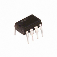
T2117-3ASY Atmel, T2117-3ASY Datasheet

T2117-3ASY
Specifications of T2117-3ASY
Available stocks
Related parts for T2117-3ASY
T2117-3ASY Summary of contents
Page 1
... Power Blinking Switch 1. Description The integrated circuit, T2117, is designed as a zero-voltage switch in bipolar technol- ogy used to control resistive loads at mains by a triac in zero-crossing mode. A ramp generator allows power control function by period group control, whereas full-wave logic guarantees that full mains cycles are used for load switching. ...
Page 2
... Trigger pulse output 7 GND Ground 8 VSYNC Voltage synchronization T2117 2 R 220 k 2 (250 V sync Ramp Synchronization generator Full-wave logic 4 - Comparator Reference voltage 1.4 V T2117 1 RAMP 2 CRAMP T2117 3 POSIN 4 NEGIN Load R 1 1000 100 µ Supply GND MT2 100 6 MT1 Pulse R 3 amplifier 8 VSYNC 7 ...
Page 3
... General Description The integrated circuit T2117 is a triac controller for zero-crossing mode designed to control power in switching resistive loads of mains supplies. Information regarding synchronous supply is provided at pin 8 via resistor R load on the mains, the full-wave logic guarantees that complete mains cycles are used for load switching ...
Page 4
... where I = Latching current of the triac Mains supply, effective Load power The total current consumption is influenced by the firing pulse width which can be calculated as follows sync T2117 4 7 – Gmax ----------------------------------- - 36 – I Gmax (see Figure 5-2 on page 5). sync ...
Page 5
... Figure 5-1. Figure 5-2. 4768B–INDCO–10/05 Output Pulse Width 10.00 V Mains 1.00 0.10 0.01 10 100 Synchronization Resistance 2000 V = 230 V ~ Mains 1600 1200 800 400 0 0 200 400 600 230 (mA) L 200 100 50 1000 10000 P (W) 800 1000 1200 1400 (µs) T2117 5 ...
Page 6
... Supply Voltage The T2117 contains a voltage limiting funtion and can be connected with the mains supply via the diode D value of 9.5 V. The series resistance R page 7 1max I tot where V = Mains voltage Limiting voltage of the Total current consumption tot I = Current requirement of the IC (without load) ...
Page 7
... Junction ambient DIP8 4768B–INDCO–10/05 Power Dissipation of R According to Current Consumption Mains Pin Symbol sync ± tot P tot amb T stg Symbol R thJA R thJA = 230 (mA) tot Value 7.3 400 125 125 0 to 100 -40 to +125 Value 200 110 T2117 Unit Unit K/W K/W 7 ...
Page 8
... Comparator Input offset voltage Input bias current Common-mode input voltage Threshold internal reference Ramp Generator, Figure 1-1 on page sync Period C = 100 µ 2.2 µ 100 k 4 Final voltage Initial voltage Charge current T2117 8 Pin Symbol - ± ±I sync 8 ±I sync ± ...
Page 9
... Applications Figure 10-1. Power Blinking Switch with 230 4768B–INDCO–10/05 2.7 Hz, Duty Cycle 1:1, Power Range 0 0.5 ... 270 k 2.2 kW 100 nF/ 250 150 k 47 µF/ 16V 1 T2117 110 k 0.47 µ T2117 9 ...
Page 10
... R = 159 (25) (15) T2117 10 270 T2117 µ 2.2 µ 220 (250 V 100 k 1 Ramp Synchronization generator ( Full-wave logic 4 - Comparator Reference voltage 1.4 V ( determines the proportional range. ( Load 1000 sync Supply 100 6 Pulse R 3 amplifier T2117 230 4768B–INDCO–10/05 ...
Page 11
... Figure 10-4. Room Temperature Control with Definite Reduction (Remote Control) for a Temperature Range 30°C L Load V = 230 4768B–INDCO–10/05 R 0.35 ... 1 1.5 kW 510 T2117 910 100 µ µ 680 680 220 9 NTC 2.2 µ µF T2117 11 ...
Page 12
... Figure 10-5. Two-point Temperature Control for a Temperature Range Load/1000 230 VDR N T2117 12 220 T2117 µ 1.5 W 220 k (680 k ) 500 (200 k ) NTC 4768B–INDCO–10/05 ...
Page 13
... Figure 10-6. Two-point Temperature Control for a Temperature and a Hysteresis of ±0 Load/400 V = 230 11. Ordering Information Extended Type Number T2117-3ASY T2117-TASY T2117-TAQY 4768B–INDCO–10/05 R sync 430 T2117 330 8 µF/ 68 µ Package Remarks DIP8 Tube, Pb-free SO8 Tube, Pb-free SO8 Taped and reeled, Pb-free ...
Page 14
... Package Information Package SO8 Dimensions in mm T2117 ific a tio 5.00 4.85 1.4 0.25 0.4 0.10 1.27 3. technical drawings according to DIN specifications 5.2 4.8 3.7 0.2 3.8 6.15 5.85 4768B–INDCO–10/05 ...
Page 15
... Revision History Please note that the following page numbers referred to in this section refer to the specific revision mentioned, not to this document. Revision No. 4768B-INDCO-08/05 4768B–INDCO–10/05 History Put datasheet in a new template First page: Pb-free logo added Page 13: Ordering Information changed T2117 15 ...
Page 16
... Disclaimer: The information in this document is provided in connection with Atmel products. No license, express or implied, by estoppel or otherwise, to any intellectual property right is granted by this document or in connection with the sale of Atmel products. EXCEPT AS SET FORTH IN ATMEL’S TERMS AND CONDI- TIONS OF SALE LOCATED ON ATMEL’S WEB SITE, ATMEL ASSUMES NO LIABILITY WHATSOEVER AND DISCLAIMS ANY EXPRESS, IMPLIED OR STATUTORY WARRANTY RELATING TO ITS PRODUCTS INCLUDING, BUT NOT LIMITED TO, THE IMPLIED WARRANTY OF MERCHANTABILITY, FITNESS FOR A PARTICULAR PURPOSE, OR NON-INFRINGEMENT ...


