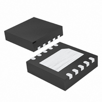
MAX17062ETB+T Maxim Integrated Products, MAX17062ETB+T Datasheet

MAX17062ETB+T
Specifications of MAX17062ETB+T
Related parts for MAX17062ETB+T
MAX17062ETB+T Summary of contents
Page 1
... Input Supply Range o Input Supply Undervoltage Lockout o Pin-Programmable 640kHz/1.2MHz Switching Frequency o Programmable Soft-Start o Improved EMI o FB Regulation Voltage Tolerance < Small 10-Pin TDFN Package o Thermal-Overload Protection PART MAX17062ETB+T + Denotes a lead-free package Exposed pad Tape and reel 2.6V TO 5.5V 6 *EP 5 Features ...
Page 2
TFT-LCD Step-Up DC-DC Converter ABSOLUTE MAXIMUM RATINGS LX to AGND ............................................................-0.3V to +22V IN, SHDN, FREQ AGND..............................-0.3V to +7.5V COMP AGND ....................................-0. PGND to AGND .....................................................-0.3V to +0.3V LX Switch Maximum Continuous RMS Current ...
Page 3
TFT-LCD Step-Up DC-DC Converter ELECTRICAL CHARACTERISTICS (continued 3V, FREQ = 3V 0°C to +85°C. Typical values are at T SHDN IN A PARAMETER CONTROL INPUTS , FREQ Input Low Voltage FREQ ...
Page 4
TFT-LCD Step-Up DC-DC Converter ELECTRICAL CHARACTERISTICS (continued 3V, FREQ = 3V -40°C to +85°C, unless otherwise noted.) (Note 1) SHDN IN A PARAMETER CONTROL INPUTS , FREQ Input Low Voltage FREQ ...
Page 5
TFT-LCD Step-Up DC-DC Converter (Circuit of Figure 5V 15V MAIN SOFT-START (R = 30Ω) LOAD 2ms/div PULSED LOAD-TRANSIENT RESPONSE (I = 100mA TO 1.1A) LOAD 10μs/div L = 2.7μ 47kΩ COMP ...
Page 6
TFT-LCD Step-Up DC-DC Converter PIN NAME Compensation Pin for Error Amplifier. Connect a series RC from COMP to ground. See the Loop 1 COMP Compensation section for component selection guidelines. Feedback Pin. The FB regulation voltage is 1.24V nominal. Connect ...
Page 7
TFT-LCD Step-Up DC-DC Converter SHDN COMP FB 1.24V FREQ OSCILLATOR 6μA Figure 2. MAX17062 Functional Diagram Detailed Description The MAX17062 is a highly efficient power supply that employs a current-mode, fixed-frequency, PWM archi- tecture for fast-transient response and low-noise opera- ...
Page 8
TFT-LCD Step-Up DC-DC Converter The MAX17062 can be programmed for soft-start upon power-up with an external capacitor. When the shutdown pin is taken high, the soft-start capacitor (C ately charged to 0.4V. Then the capacitor is charged at a constant ...
Page 9
TFT-LCD Step-Up DC-DC Converter AC characteristics of the inductor core material and the ratio of inductor resistance to other power-path resis- tances, the best LIR can shift up or down. If the induc- tor resistance is relatively high, more ripple ...
Page 10
TFT-LCD Step-Up DC-DC Converter Input Capacitor Selection The input capacitor (C ) reduces the current peaks IN drawn from the input supply and reduces noise injection into the IC. Two 4.7μF ceramic capacitors are used in the Typical Operating Circuit ...
Page 11
TFT-LCD Step-Up DC-DC Converter VGOFF -15V C11 0.22μ 4. 4.7μF 4.7μF 10Ω 10V 10V 1μF Figure 3. Multiple-Output TFT-LCD Power Supply Multiple-Output Power Supply for TFT-LCD Figure 3 shows a power supply for active-matrix ...
Page 12
TFT-LCD Step-Up DC-DC Converter 3) Place the feedback voltage-divider-resistors as close to the FB pin as possible. The divider’s center trace should be kept short. Placing the resistors far away causes the FB trace to become an antenna that can ...
Page 13
TFT-LCD Step-Up DC-DC Converter (The package drawing(s) in this data sheet may not reflect the most current specifications. For the latest package outline information www.maxim-ic.com/packages.) ______________________________________________________________________________________ Package Information 13 ...
Page 14
... Maxim cannot assume responsibility for use of any circuitry other than circuitry entirely embodied in a Maxim product. No circuit patent licenses are implied. Maxim reserves the right to change the circuitry and specifications without notice at any time. 14 ____________________Maxim Integrated Products, 120 San Gabriel Drive, Sunnyvale, CA 94086 408-737-7600 © 2007 Maxim Integrated Products ...


