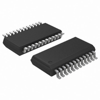
ADT7476ARQZ ON Semiconductor, ADT7476ARQZ Datasheet - Page 22

ADT7476ARQZ
Manufacturer Part Number
ADT7476ARQZ
Description
IC REMOTE THERMAL CTRLR 24QSOP
Manufacturer
ON Semiconductor
Series
dBCool®r
Datasheet
1.ADT7476ARQZ-REEL.pdf
(67 pages)
Specifications of ADT7476ARQZ
Function
Fan Control, Temp Monitor
Topology
ADC, Comparator, Fan Speed Counter, Multiplexer, Register Bank
Sensor Type
External & Internal
Sensing Temperature
-40°C ~ 125°C, External Sensor
Output Type
SMBus™
Output Alarm
No
Output Fan
Yes
Voltage - Supply
3 V ~ 3.6 V
Operating Temperature
-40°C ~ 125°C
Mounting Type
Surface Mount
Package / Case
24-QSOP
Full Temp Accuracy
+/- 0.5 C
Digital Output - Bus Interface
Serial (3-Wire, 4-Wire)
Maximum Operating Temperature
+ 125 C
Minimum Operating Temperature
- 40 C
Lead Free Status / RoHS Status
Lead free / RoHS Compliant
Available stocks
Company
Part Number
Manufacturer
Quantity
Price
Part Number:
ADT7476ARQZ
Manufacturer:
ADI/亚德诺
Quantity:
20 000
Part Number:
ADT7476ARQZ-REEL
Manufacturer:
ON/安森美
Quantity:
20 000
Company:
Part Number:
ADT7476ARQZ-REEL7
Manufacturer:
ON
Quantity:
6 028
Bit 5 (F4P) = 1, indicates Fan 4 has dropped below minimum
speed. Alternatively, indicates that the THERM limit has
been exceeded, if the THERM function is used.
Alternatively, indicates the status of GPIO6.
Bit 4 (FAN3) = 1, indicates Fan 3 has dropped below
minimum speed.
Bit 3 (FAN2) = 1, indicates Fan 2 has dropped below minimum
speed.
Bit 2 (FAN1) = 1, indicates Fan 1 has dropped below minimum
speed.
Bit 1 (OVT) = 1, indicates a THERM overtemperature limit
has been exceeded.
Bit 0 (12 V/VC) = 1, indicates a 12 V high or low limit has
been exceeded. If the VID code change function is used, this
bit indicates a change in VID code on the VID0 to VID4
inputs.
SMBALERT Interrupt Behavior
interrupt can be generated for out−of−limit conditions. It is
important to note how the SMBALERT output and status
bits behave when writing interrupt handler software.
status bits behave. Once a limit is exceeded, the
corresponding status bit is set to 1. The status bit remains set
until the error condition subsides and the status register is
read. The status bits are referred to as sticky because they
remain set until read by software. This ensures that an
out−of−limit event cannot be missed if the software is
periodically polling the device.
Note that:
•
•
HIGH LIMIT
TEMPERATURE
STATUS BIT
SMBALERT
The ADT7476 can be polled for status, or an SMBALERT
Figure 29 shows how the SMBALERT output and sticky
The SMBALERT output remains low for the entire
duration that a reading is out−of−limit and until the
status register has been read. This has implications on
how software handles the interrupt.
THERM overtemperature events are not sticky. They
reset immediately after the overtemperature condition
ceases.
STICKY
Figure 29. SMBALERT and Status Bit Behavior
TEMP BACK IN LIMIT
(STATUS BIT STAYS SET)
(TEMP BELOW LIMIT)
CLEARED ON READ
http://onsemi.com
22
Handling SMBALERT Interrupts
interrupts, it is recommend to handle the SMBALERT
interrupt as follows:
Masking Interrupt Sources
Register 2 (0x75) allow individual interrupt sources to be
masked to prevent SMBALERT interrupts. Note: Masking
an interrupt source prevents only the SMBALERT output
from being asserted; the appropriate status bit is set
normally.
Interrupt Mask Register 1 (0x74)
Bit 7 (OOL) = 1, masks SMBALERT for any alert condition
flagged in Interrupt Status Register 2.
Bit 6 (R2T) = 1, masks SMBALERT for Remote 2 temperature.
Bit 5 (LT) = 1, masks SMBALERT for local temperature.
Bit 4 (R1T) = 1, masks SMBALERT for Remote 1 temperature.
Bit 3 (5.0 V) = 1, masks SMBALERT for 5.0 V channel.
Bit 2 (V
Bit 1 (V
Bit 0 (2.5 V) = 1, masks SMBALERT for 2.5 V
Figure 30. How Masking the Interrupt Source Affects
HIGH LIMIT
TEMPERATURE
STATUS BIT
SMBALERT
To prevent the system from being tied up servicing
Interrupt Mask Register 1 (0x74) and Interrupt Mask
STICKY
1. Detect the SMBALERT assertion.
2. Enter the interrupt handler.
3. Read the status registers to identify the interrupt
4. Mask the interrupt source by setting the
5. Take the appropriate action for a given interrupt
6. Exit the interrupt handler.
7. Periodically poll the status registers. If the
source.
appropriate mask bit in the interrupt mask registers
(0x74 and 0x75).
source.
interrupt status bit has cleared, reset the
corresponding interrupt mask bit to 0. This causes
the SMBALERT output and status bits to behave
as shown in Figure 30.
CC
CCP
) = 1, masks SMBALERT for V
) = 1, masks SMBALERT for V
SMBALERT Output
TEMP BACK IN LIMIT
(STATUS BIT STAYS SET)
INTERRUPT
MASK BIT SET
(TEMP BELOW LIMIT)
CLEARED ON READ
(SMBALERT REARMED)
INTERRUPT MASK BIT
CC
CCP
CLEARED
channel.
IN
channel.
/ THERM.


