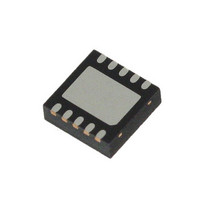
L6728AHTR STMicroelectronics, L6728AHTR Datasheet - Page 23

L6728AHTR
Manufacturer Part Number
L6728AHTR
Description
IC CTLR PWM SGL PHASE 10-VFQFPN
Manufacturer
STMicroelectronics
Datasheet
1.L6728AHTR.pdf
(33 pages)
Specifications of L6728AHTR
Pwm Type
Voltage Mode
Number Of Outputs
1
Frequency - Max
660kHz
Duty Cycle
67%
Voltage - Supply
5 V ~ 12 V
Buck
Yes
Boost
No
Flyback
No
Inverting
No
Doubler
No
Divider
No
Cuk
No
Isolated
No
Operating Temperature
-40°C ~ 125°C
Package / Case
10-VFQFN, 10-VFQFPN
Frequency-max
660kHz
Lead Free Status / RoHS Status
Lead free / RoHS Compliant
Other names
497-8977-2
Available stocks
Company
Part Number
Manufacturer
Quantity
Price
Company:
Part Number:
L6728AHTR
Manufacturer:
PHI
Quantity:
1 800
Company:
Part Number:
L6728AHTR
Manufacturer:
STMicroelectronics
Quantity:
10 000
Part Number:
L6728AHTR
Manufacturer:
ST
Quantity:
20 000
L6728AH
11.1
11.1.1
11.1.2
Note:
11.1.3
11.1.4
Demonstration board description
Power input (V
This is the input voltage for the power conversion. The high-side drain is connected to this
input. This voltage can range from 1.5 V to 12 V bus.
If the voltage is between 5 V and 12 V it can supply also the device (through the V
and in this case the R16 (0 Ω) resistor must be present.
Output (V
Different output voltage rails have been tested. For each rail a few component need to be
changed: these components are used to program the desiderated output voltage and to
compensate the system. The over-current-protection limit is set to ~27 A but it can be
changed by replacing the resistors R18.
Table 7.
All the previous resistors are SMD 0603 package, 1/16W, 1% tolerance.
Signal input (V
Using the input voltage V
However the controller can be supplied separately from the power stage through the V
input and, in this case, the R16 (0 Ω) resistor must be unsoldered.
Test points
Several test points are provided to have easy access at all important signal characterizing
the device:
R8, R13
R6, R9
Ref.
–
–
–
–
–
–
–
Q9
R7
COMP: The output of the error amplifier;
FB: The inverting input of the error amplifier;
PGOOD: Signaling the regular functioning (active high);
VGDHS: The bootstrap diode anode;
PHASE: Phase node;
LGATE: Low-side gate pin of the device;
HGATE: High-side gate pin of the device.
OUT
Rail dependent components
8 V rail
3.6 kΩ
3.6 kΩ
)
390 Ω
IN
CC
)
Mounted
)
IN
to supply the controller no power is required at this input.
5 V rail
3.6 kΩ
3.6 kΩ
680 Ω
Doc ID 15726 Rev 1
3.3 V rail
3.6 kΩ
4.7 kΩ
1.5 kΩ
2.5 V rail
3.6 kΩ
4.7 kΩ
2.2 kΩ
Not mounted
20 A demonstration board
1.25 V rail
11 kΩ
22 kΩ
39 kΩ
0.8 V rail
CC
11 kΩ
22 kΩ
Open
pin)
CC
23/33


