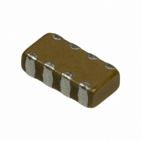
GNM314R72A102KD01D Murata Electronics North America, GNM314R72A102KD01D Datasheet - Page 84

GNM314R72A102KD01D
Manufacturer Part Number
GNM314R72A102KD01D
Description
CAP 4-ARRAY 1000PF 100V X7R 1206
Manufacturer
Murata Electronics North America
Series
GNMr
Datasheet
1.GNM212R61A225MA01D.pdf
(151 pages)
Specifications of GNM314R72A102KD01D
Capacitance
1000pF
Voltage - Rated
100V
Dielectric Material
Ceramic
Number Of Capacitors
4
Circuit Type
Isolated
Temperature Coefficient
X7R
Tolerance
±10%
Mounting Type
Surface Mount
Package / Case
1206 (3216 Metric)
Height
0.031" (0.80mm)
Size / Dimension
0.126" L x 0.063" W (3.20mm x 1.60mm)
Lead Free Status / RoHS Status
Lead free / RoHS Compliant
Other names
490-3421-2
- Current page: 84 of 151
- Download datasheet (3Mb)
13
!Note
• This PDF catalog is downloaded from the website of Murata Manufacturing co., ltd. Therefore, it’s specifications are subject to change or our products in it may be discontinued without advance notice. Please check with our
• This PDF catalog has only typical specifications because there is no space for detailed specifications. Therefore, please approve our product specifications or transact the approval sheet for product specifications before ordering.
sales representatives or product engineers before ordering.
!Note
Chip monolithic ceramic capacitors (chips) can
experience degradation of termination solderability
when subjected to high temperature or humidity, or if
exposed to sulfur or chlorine gases.
Storage environment must be at an ambient temperature
of 5-40 degree C and an ambient humidity of 20-70%RH.
Use chip within 6 months. If 6 months or more have
elapsed, check solderability before use.
1. Inspection
2. Board Separation (or depanalization)
82
!Caution
(1) Board flexing at the time of separation causes
(2) Severity of stresses imposed on the chip at the
(3) Board separation must be performed using special
Thrusting force of the test probe can flex the PCB,
Storage and Operating Conditions
Handling
resulting in cracked chips or open solder joints.
Provide support pins on the back side of the PCB to
prevent warping or flexing.
cracked chips or broken solder.
time of board break is in the order of:
Pushback<Slitter<V Slot<Perforator.
jigs, not with hands.
• Please read rating and !CAUTION (for storage, operating, rating, soldering, mounting and handling) in this catalog to prevent smoking and/or burning, etc.
• This catalog has only typical specifications because there is no space for detailed specifications. Therefore, please approve our product specifications or transact the approval sheet for product specifications before ordering.
Use of Sn-Zn based solder will deteriorate
reliability of MLCC.
Please contact Murata factory for the use of Sn-Zn
based solder in advance.
FAILURE TO FOLLOW THE ABOVE CAUTIONS MAY
RESULT, WORST CASE, IN A SHORT CIRCUIT
AND CAUSE FUMING OR PARTIAL DISPERSION
WHEN THE PRODUCT IS USED.
3. Reel and bulk case
FAILURE TO FOLLOW THE ABOVE CAUTIONS MAY
RESULT, WORST CASE, IN A SHORT CIRCUIT
AND FUMING WHEN THE PRODUCT IS USED.
In the handling of reel and case, please be careful
and do not drop it.
Do not use chips from a case which has been dropped.
C02E.pdf
07.2.6
Related parts for GNM314R72A102KD01D
Image
Part Number
Description
Manufacturer
Datasheet
Request
R

Part Number:
Description:
BUZZER PIEZO 25VP-P SMD
Manufacturer:
Murata Electronics North America

Part Number:
Description:
CAP 4-ARRAY 680PF 100V X7R 1206
Manufacturer:
Murata Electronics North America
Datasheet:

Part Number:
Description:
CAP 4-ARRAY 1800PF 100V X7R 1206
Manufacturer:
Murata Electronics North America
Datasheet:

Part Number:
Description:
CAP 4-ARRAY 68000PF 16V X7R 1206
Manufacturer:
Murata Electronics North America
Datasheet:

Part Number:
Description:
CAP CER 1000PF 50V 10% X7R 0402
Manufacturer:
Murata Electronics North America
Datasheet:

Part Number:
Description:
CAP CER 10000PF 16V 10% X7R 0402
Manufacturer:
Murata Electronics North America
Datasheet:

Part Number:
Description:
CAP 5.5-25PF 2.5X3.2MM SMD
Manufacturer:
Murata Electronics North America
Datasheet:

Part Number:
Description:
CAP 4.5-20PF 2.5X3.2MM SMD
Manufacturer:
Murata Electronics North America
Datasheet:

Part Number:
Description:
CAP 5.0-20PF 3.2X4.5MM SMD RED
Manufacturer:
Murata Electronics North America
Datasheet:

Part Number:
Description:
CAP 2.0-6.0PF 3.2X4.5MM SMD BLU
Manufacturer:
Murata Electronics North America
Datasheet:

Part Number:
Description:
CAP 1.4-3.0PF 3.2X4.5MM SMD BRN
Manufacturer:
Murata Electronics North America
Datasheet:

Part Number:
Description:
CAP 3.0-10PF 3.2X4.5MM SMD WHT
Manufacturer:
Murata Electronics North America
Datasheet:

Part Number:
Description:
CAP 2.0-6.0PF 4X4.5MM TOPADJ BLU
Manufacturer:
Murata Electronics North America
Datasheet:

Part Number:
Description:
CAP 8.5-40PF 4X4.5MM TOPADJ YEL
Manufacturer:
Murata Electronics North America
Datasheet:

Part Number:
Description:
CAP 8.0-45PF 2.5X3.2MM SMD
Manufacturer:
Murata Electronics North America
Datasheet:


