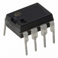
MC34063EBN STMicroelectronics, MC34063EBN Datasheet

MC34063EBN
Specifications of MC34063EBN
MC34063EBN
Available stocks
Related parts for MC34063EBN
MC34063EBN Summary of contents
Page 1
... Employing a minimum number of external components the MC34063A/E devices series is Table 1. Device summary DIP-8 MC34063ABN MC34063ACN MC34063EBN MC34063ECN 1. The "A" version is not recommended for new designs. November 2007 MC34063AB - MC34063AC MC34063EB - MC34063EC DC/DC converter control circuits designed for step-down, step-up and voltage- inverting applications ...
Page 2
Contents 1 Diagram . . . . . . . . . . . . . . . . . . . . . . . . . . . . . . . . . . . . . ...
Page 3
Diagram Figure 1. Block diagram 3/23 ...
Page 4
Pin configuration Figure 2. Pin connections Table 2. Pin description Pin n° Symbol 1 SWC 2 SWE GND 5 CII DRC 4/23 Name and function Switch collector Switch emitter ...
Page 5
Maximum ratings Table 3. Absolute maximum ratings Symbol V Power supply voltage CC V Comparator input voltage range IR V Switch collector voltage SWC V Switch emitter voltage (V SWE V Switch collector to emitter voltage CE V Driver ...
Page 6
Electrical characteristics (Refer to the test circuits, V Note 2) Table 5. Oscillator Symbol Parameter f Frequency OSC I Charge current CHG I Discharge current DISCHG Discharge to charge I /I DISCHG CHG current ratio V Current limit sense ...
Page 7
Table 8. Total device Symbol Parameter I Supply current CC V Start-up voltage (Note START-UP Note: 1 Maximum package power dissipation limit must be observed °C, T LOW HIGH T = -40 °C, T LOW HIGH ...
Page 8
Typical performance characteristics Figure 3. Emitter follower configuration output saturation voltage vs emitter current Figure 5. Common emitter configuration output switch saturation voltage vs collector current 8/23 Figure 4. Output switch ON-OFF time vs oscillator timing capacitor Figure 6. ...
Page 9
Figure 7. Power collector emitter saturation voltage ( temperature CEsat Figure 9. Reference voltage vs temperature Figure 11. Supply current vs temperature Figure 8. Current limit sense voltage (V vs temperature Figure 10. Bias current vs temperature Figure ...
Page 10
Typical application circuit Figure 13. Step-up converter Figure 14. Printed evaluation board Table 9. Test condition (V OUT Test Line Regulation Load Regulation Output Ripple ...
Page 11
Figure 15. Step-down converter Figure 16. Printed evaluation board Table 10. Test condition (V OUT Test Line regulation Load regulation Output ripple ...
Page 12
Figure 17. Voltage inverting converter Figure 18. Printed evaluation board Table 11. Test condition (V OUT Test Line regulation Load regulation Output ripple ...
Page 13
Table 12. Calculation Step-Up Parameter (Discontinuous mode OUT t /t ------------------------------------------------ on off min ( max 1/f on off C 4.5x10 PK(switch) out(max) R 0.3/I SC PK(switch) I out ...
Page 14
Figure 19. Step-up with external NPN switch Figure 20. Step-down with external NPN switch 14/23 ...
Page 15
Figure 21. Step-down with external PNP switch Figure 22. Voltage inverting with external NPN switch 15/23 ...
Page 16
Figure 23. Voltage inverting with external PNP saturated switch Figure 24. Dual output voltage 16/23 ...
Page 17
Figure 25. Higher output power, higher input voltage 17/23 ...
Page 18
Package mechanical data In order to meet environmental requirements, ST offers these devices in ECOPACK® packages. These packages have a lead-free second level interconnect. The category of second level interconnect is marked on the package and on the inner ...
Page 19
Plastic DIP-8 mechanical data mm. Dim. Min. Typ. A 3.3 a1 0.7 B 1.39 B1 0.91 b 0 8.8 e 2.54 e3 7. 3.3 Z 0.44 inch. Max. Min. Typ. 0.130 ...
Page 20
Dim. Min. A 1.35 A1 0.10 A2 1.10 B 0.33 C 0.19 D 4. 5.80 h 0.25 L 0.40 k ddd 20/23 SO-8 mechanical data mm. Typ. Max. 1.75 0.25 1.65 0.51 0.25 5.00 4.00 1.27 ...
Page 21
Tape & reel SO-8 mechanical data mm. Dim. Min. Typ 12 8.1 Bo 5.5 Ko 2.1 Po 3.9 P 7.9 inch. Max. Min. Typ. 330 13.2 0.504 0.795 2.362 22.4 8.5 0.319 ...
Page 22
Revision history Table 13. Document revision history Date Revision 22-Jun-2004 9 20-Nov-2007 10 22/23 Changes Added Table 1. ...
Page 23
... Information in this document is provided solely in connection with ST products. STMicroelectronics NV and its subsidiaries (“ST”) reserve the right to make changes, corrections, modifications or improvements, to this document, and the products and services described herein at any time, without notice. All ST products are sold pursuant to ST’s terms and conditions of sale. ...


