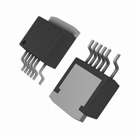
DPA425R Power Integrations, DPA425R Datasheet

DPA425R
Specifications of DPA425R
Available stocks
Related parts for DPA425R
DPA425R Summary of contents
Page 1
... DPA-Switch DC-DC forward converter design utility that is included in the software design tool, PI Expert. Subsequent application notes will provide comprehensive procedures for designs of greater complexity. Designers are advised to check Power Integrationsʼ website at www.powerint.com for the latest application information and design tools. Snubber ...
Page 2
AN-31 Description Input Input Voltage Input Voltage UV Turn ON Input Voltage UV Turn Off Input Voltage OV Turn On Input Voltage OV Turn Off Output Output Voltage Output Ripple and Noise Output Current Line Regulation Load Regulation Transient Response ...
Page 3
DPA-Switch D L CONTROL CONTROL Input Derived (a) + DPA-Switch D L CONTROL CONTROL Output Coupled Inductor Bias (c) Figure 2. Methods for Generation of Bias Voltage. Output Rectifiers Output ...
Page 4
AN-31 Efficiency Designing a DC-DC converter with DPA-Switch involves several engineering tradeoffs that weigh efficiency against cost and complexity. The circuit configuration in Figure 1 achieves efficiencies greater than 85% over the range of input voltage at medium loads. In ...
Page 5
Input Voltage Bias Type Range (V) DC Input Derived Bias Transfer Bias (unregulated) Output Coupled Inductor Bias Transformer Bias (regulated) Table 2. Bias Voltage Solution Comparison. of input ...
Page 6
AN-31 90% 88% 86% 84% 82% 80 Input Voltage Figure 3. Efficiency of the Low Cost EP-21 Prototype with Different Devices in the DPA-Switch Family (Synchronous Rectification Would Improve Efficiency). If the transformer ...
Page 7
If power dissipation is a problem with the smallest device, select the next larger device and program the current limit with the X pin to 10% above the peak primary current. This is done to limit overload power capability. Refer ...
Page 8
AN-31 C3, C4, C5 µF, IN 100 V (x4) 36-72 VDC L1 J1-1 1 µH 2 UF4003 C8 470 pF 200 µF 1 µF 100 V 100 V L2 100 µH ...
Page 9
T S 200 150 100 50 0 -50 -100 2.5 0 Time (µs) (a) 300 250 200 150 100 50 0 -50 -100 2.5 0 Time (µs) (b) 300 250 200 150 ...
Page 10
AN-31 the transformer increases in the positive direction during t and resets to zero during the interval the magnetizing inductance is removed during t the reset capacitor and the clamp capacitor to maximum voltage. The flux increases ...
Page 11
DPA-Switch U1 D CONTROL CONTROL Figure 9. Essential Components of the Feedback Circuit. The Schematic Does Not Show ESR of the Output Capacitors (Component Designators are the Same as in the EP-21 Prototype). The phase margin is ...
Page 12
AN-31 60 1-Gain 56 dB Loop Gain Degrees Phase 30 180 Degrees Phase Margin 1-Phase -10 -20 -30 -40 P1 -50 -60 0.1 1 Figure 10. Gain and Phase of a Typical Feedback Loop ...
Page 13
The zero introduced by R4 and the ESR of C6 should be at approximately 25% of the output filter resonant frequency. This ...
Page 14
... Si4888 Si4888 BAV19WS 4.7 µ DPA-Switch PC357N1T DPA425R 1.0 Ω 18.2 kΩ 220 nF 68 µ The two modes have different control characteristics. The converter in discontinuous conduction mode will usually have a slower response to transients and higher ripple voltage at the output than in continuous conduction mode. In extreme cases, a ...
Page 15
R15 Q1 Q2 (a) C17 R15 R16 (b) Figure 12. Synchronous Rectification (a) Winding Driven DC Coupled. (b) Winding Driven AC Coupled. output. For output, an efficiency of 85% with Schottky rectifiers would typically ...
Page 16
AN-31 Synchronous Rectifier Type Winding Driven DC Coupled Winding Driven AC Coupled Active Drive Table 4. Comparison of Synchronous Rectification Techniques. winding. Capacitor C17 should be chosen to capacitively divide the winding voltage between C17 and the C Q2, to ...
Page 17
Solder Side Component Side TOP VIEW V + DPA-Switch - Maximize hatched copper area for optimum heat sinking Via between board layers V Figure 13. Layout Considerations for DPA-Switch Using R Package. board material is used (such as FR4), providing ...
Page 18
AN-31 4. Thermal check – At maximum output power, minimum input voltage and maximum ambient temperature, verify that temperature specifications are not exceeded for the transformer, output diodes, output inductors and output capacitors. The DPA-Switch is fully protected against overtemperature ...
Page 19
AN- 7/04 ...
Page 20
... For the latest updates, visit our Web site: www.powerint.com Power Integrations may make changes to its products at any time. Power Integrations has no liability arising from your use of any information, device or circuit described herein nor does it convey any license under its patent rights or the rights of others. POWER INTEGRATIONS MAKES NO WARRANTIES HEREIN AND SPECIFICALLY DISCLAIMS ALL WARRANTIES INCLUDING, WITHOUT LIMITATION, THE IMPLIED WARRANTIES OF MERCHANTABILITY, FITNESS FOR A PARTICULAR PURPOSE, AND NON-INFRINGEMENT OF THIRD PARTY RIGHTS ...


