L6756D STMicroelectronics, L6756D Datasheet
L6756D
Specifications of L6756D
Available stocks


Related parts for L6756D


L6756D Summary of contents
Page 1
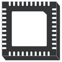
... Low-side-less start-up allows soft-start over pre- biased output avoiding dangerous current return through the main inductors as well as negative spike at the load side. L6756D is available in VFQFPN 6x6 mm package Package VFQFPN40 VFQFPN40 Rev 1 L6756D ® ...
Page 2
... Output voltage load-line definition . . . . . . . . . . . . . . . . . . . . . . . . . . . . . . 22 5.4 Output voltage offset . . . . . . . . . . . . . . . . . . . . . . . . . . . . . . . . . . . . . . . . 22 5.5 Dynamic VID transitions . . . . . . . . . . . . . . . . . . . . . . . . . . . . . . . . . . . . . . 23 5.6 Soft-start . . . . . . . . . . . . . . . . . . . . . . . . . . . . . . . . . . . . . . . . . . . . . . . . . . 24 5.6.1 6 Output voltage monitoring and protections . . . . . . . . . . . . . . . . . . . . . 26 6.1 Overvoltage . . . . . . . . . . . . . . . . . . . . . . . . . . . . . . . . . . . . . . . . . . . . . . . 26 6.2 Feedback disconnection . . . . . . . . . . . . . . . . . . . . . . . . . . . . . . . . . . . . . . 26 6.3 VR_RDY . . . . . . . . . . . . . . . . . . . . . . . . . . . . . . . . . . . . . . . . . . . . . . . . . . 27 6.4 Over current . . . . . . . . . . . . . . . . . . . . . . . . . . . . . . . . . . . . . . . . . . . . . . . 27 7 Low power-state management and PSI Main oscillator . . . . . . . . . . . . . . . . . . . . . . . . . . . . . . . . . . . . . . . . . . . . . 29 2/36 LSLESS start- L6756D ...
Page 3
... L6756D 9 System control loop compensation . . . . . . . . . . . . . . . . . . . . . . . . . . . 30 9.1 Compensation network guidelines . . . . . . . . . . . . . . . . . . . . . . . . . . . . . . 31 9.2 LTB Technology 10 Mechanical data and package dimensions . . . . . . . . . . . . . . . . . . . . . . 34 11 Revision history . . . . . . . . . . . . . . . . . . . . . . . . . . . . . . . . . . . . . . . . . . . 35 ® Contents 3/36 ...
Page 4
... Typical application circuit and block diagram 1 Typical application circuit and block diagram 1.1 Application circuit Figure 1. Typical 4phase application circuit 4/36 L6756D ...
Page 5
... L6756D Figure 2. Typical 3phase application circuit Typical application circuit and block diagram 5/36 ...
Page 6
... Typical application circuit and block diagram Figure 3. Typical 2phase application circuit 6/36 L6756D ...
Page 7
... L6756D 1.2 Block diagram Figure 4. Block diagram Typical application circuit and block diagram 7/36 ...
Page 8
... Connect 27 kΩ resistor to program T2 = 500 µs. The same slope implemented to reach V BOOT reference moves from V to the programmed VID code. The pin is kept to a BOOT fixed 1.24 V. Function Table 6) or VR11 has to be considered also when the L6756D ...
Page 9
... L6756D Table 2. Pin description (continued) Pin# Name 12 ROSC 13 ILIM 14 GND 15 LTB 16 FBG 17 VSEN 18 COMP 19 VFB 20 VDRP 21 CS1N 22 CS1 23 CS2N 24 CS2 25 CS3N 26 CS3 27 CS4N Pins description and connection diagrams Oscillator pin. It allows programming the switching frequency F channel: the equivalent switching frequency at the load side results in being multiplied by the phase number N ...
Page 10
... CPU from excessive voltages. Thermal pad connects the silicon substrate and makes good thermal contact with the PCB. Connect to the PGND plane. Function gain pin. See Section 9.2 for details. Section 7 for details. to FBG to implement a load MON L6756D ...
Page 11
... L6756D 2.2 Thermal data Table 3. Thermal data Symbol Thermal resistance junction to ambient R thJA (Device soldered on 2s2p PC board) R Thermal resistance junction to case thJC T Maximum junction temperature MAX T Storage temperature range STG T Junction temperature range J Pins description and connection diagrams Parameter Value Unit 35 ° ...
Page 12
... Min. Typ. Max. 25 9.75 7 185 200 215 500 1 400 500 600 100 200 300 1.026 1.081 1.136 0.80 0.85 0.90 100 -0.5 0.5 CORE -40 -50 -60 130 25 0.3 0.8 L6756D Unit V V Unit kHz kHz μs μ μA dB V/μ ...
Page 13
... L6756D Table 5. Electrical characteristics (continued ± Symbol Parameter PSI#/VR10 Input threshold VREF Reference voltage LTBGAIN LTBGAIN voltage Differential current sense and current monitor k DROOP accuracy IDROOP k IMON accuracy IMON k ILIM accuracy ILIM PWM outputs Output high Gx Output low I Test current ...
Page 14
... A 1.05000 1.04375 1.03750 1.03125 1.02500 1.01875 1.01250 1.00625 A L6756D Output HEX code Output voltage VID[7:0] voltage 0 0.81250 C 0 0.41250 1 0.80625 C 1 0.40625 2 0.80000 C 2 0.40000 3 0.79375 C 3 0.39375 4 0.78750 C 4 0.38750 5 0.78125 C 5 0.38125 6 0.77500 C 6 0.37500 7 0.76875 ...
Page 15
... L6756D Table 6. Voltage identification (VID) for Intel VR11.x mode (continued) HEX code Output VID[7:0] voltage 2 2 1.40000 2 3 1.39375 2 4 1.38750 2 5 1.38125 2 6 1.37500 2 7 1.36875 2 8 1.36250 2 9 1.35625 2 A 1.35000 2 B 1.34375 2 C 1.33750 2 D 1.33125 2 E 1.32500 ...
Page 16
... L6756D Output voltage 1 1.20000 0 1.19375 1 1.18750 0 1.18125 1 1.17500 0 1.16875 1 1.16250 0 1.15625 1 1.15000 0 1.14375 1 1.13750 0 1.13125 1 1.12500 0 1.11875 1 1.11250 0 1.10625 1 1.10000 0 1.09375 1 OFF 0 OFF 1 OFF 0 OFF 1 1.08750 0 1.08125 1 1.07500 0 1.06875 1 1.06250 0 1.05625 1 1.05000 0 1.04375 1 1.03750 0 1.03125 1 1.02500 0 1.01875 ...
Page 17
... L6756D Table 7. Voltage identifications (VID) for Intel VR10 mode + 6.25 mV (continued) VID4 VID3 VID2 VID1 VID0 VID5 VID6 Output VID4 VID3 VID2 VID1 VID0 VID5 VID6 voltage 1.38750 1.38125 1.37500 1.36875 1.36250 1.35625 1.35000 1.34375 1.33750 1.33125 1.32500 1.31875 1.31250 1.30625 ...
Page 18
... Electrical specifications Table 8. Gate output connections for phase # definition Mode 2-phase 3-phase 4-phase 18/36 Gate output connections driver GND to driver to driver to driver to driver L6756D driver GND to driver GND to driver to driver ...
Page 19
... L6756D permits easy system design by allowing current reading across inductor in fully differential mode. Also a sense resistor in series to the inductor can be considered to improve reading precision. The current information read corrects the PWM output in order to equalize the average current carried by each phase ...
Page 20
... R connected. OS L6756D allows to recover from GND losses in order to regulate remotely the programmed voltage without any additional external components. In this way, the output voltage programmed is regulated compensating for board and socket losses. Keeping the sense traces parallel and guarded by a power plane results in common mode coupling for any picked-up noise ...
Page 21
... Current reading and current sharing loop L6756D embeds a flexible, fully-differential current sense circuitry that is able to read across inductor parasitic resistance or across a sense resistor placed in series to the inductor ele- ment. The fully-differential current reading rejects noise and allows placing sensing element in different locations without affecting the measurement's accuracy ...
Page 22
... Output voltage positioning 5.3 Output voltage load-line definition L6756D is able to introduce a dependence of the output voltage on the load current recovering part of the drop due to the output capacitor ESR in the load transient. Introducing a dependence of the output voltage on the load current, a static error, proportional to the output current, causes the output voltage to vary according to the sensed current ...
Page 23
... L6756D 5.5 Dynamic VID transitions L6756D manages dynamic VID transitions that allow the output voltage to modify during normal device operation for CPU power management purposes. OV and UV signals are properly masked during every DVID Transition and they are re-activated with a 16 clock cycle delay to prevent from false triggering ...
Page 24
... Output voltage positioning 5.6 Soft-start L6756D implements a soft-start to smoothly charge the output filter avoiding high in-rush currents to be required to the input power supply. During this phase, the device increases the reference from zero up to the programmed reference in closed loop regulation. Soft-start is implemented only when all the power supplies are above their own turn-on thresholds and the EN pin is set free ...
Page 25
... L6756D 5.6.1 LSLESS start-up In order to avoid any kind of negative undershoot on the load side during start-up, L6756D performs a special sequence in enabling the drivers for both sections: during the soft-start phase, the LS driver results to be disabled (LS = OFF - Gx set to HiZ and DRVON = 0) until the first PWM pulse. After the first PWM pulse, Gx outputs switches between logic “0” and logic “ ...
Page 26
... Output voltage monitoring and protections 6 Output voltage monitoring and protections L6756D monitors through pin VSEN the regulated voltage in order to manage OV and UV. The device shows different thresholds when in different operative conditions but the behavior in response to a protection event is still the same as described below. ...
Page 27
... DCR). Moreover, since also the internal threshold spreads, the design has to consider the minimum/maximum value of the thresholds. L6756D monitors the average current and allows to set the OC threshold by programming R . ILIM pin allows to define a maximum average output current for the system (I ILIM copy of the DROOP current is sourced from the ILIM pin ...
Page 28
... Figure 12. System efficiency enhancement by PSI# 28/36 PSI Strategy No strategy. IC will work in VR11 mode Phase number set to 2 while PSI# is asserted (only phase1 and Phase3 are active). Phase number set to 1 while PSI# is asserted (only phase1 is active). Table 9, by programming different PSI#/VR10 VR10 PSI# L6756D ...
Page 29
... L6756D 8 Main oscillator The internal oscillator generates the triangular waveform for the PWM charging and discharging with a constant current an internal capacitor. The switching frequency for each channel internally fixed at 200 kHz: the resulting switching frequency at the load SW side results in being multiplied by N (number of configured phases). ...
Page 30
... ESR 30/36 Figure ⋅ ⋅ PWM ⎛ ⎞ ⋅ -------------- + + ----------- - ⎝ ⎠ ------------------ - is the PWM transfer function. ΔV OSC (s), the transfer function has one zero and two fixed by ESR and the droop resistance. 14. ⋅ FB L6756D ) LC ...
Page 31
... L6756D Figure 15. Control loop bode diagram and fine tuning To obtain the desired shape an R implementation. A zero at ω integrator minimizes the static error while placing the zero ω C resonance assures a simple -20 dB/dec shape of the gain. In fact, considering the usual value for the output filter, the LC resonance results frequency lower than the above reported zero. Compensation network can be simply designed placing ω ...
Page 32
... Load- control loop is reported in Figure ® control loop network. After detecting a load transient, the LTB ramp is reset and LTB significantly speeds-up the transient FB ) can also be used. I 16. L6756D ® ...
Page 33
... L6756D Sensitivity of the load transient detector and the gain of the LTB ramp can be programmed in order to control precisely both the undershoot and the ring-back. ● Detector design. R which is desired the controller to be sensitive as follow: dV OUT R = ----------------- - LTB 25μA ● Gain design. Through the LTBGAIN pin it is possible to modify the slope of the LTB Ramp in order to modulate the entity of the LTB response once the LT has been detected ...
Page 34
... OUTLINE AND MECHANICAL DATA VFQFPN-40 (6x6x1.0mm) Very Fine Quad Flat Package No lead ddd L6756D ® ...
Page 35
... L6756D 11 Revision history Table 10. Document revision history Date 01-Oct-2008 Revision 1 Initial release Revision history Changes 35/36 ...
Page 36
... Australia - Belgium - Brazil - Canada - China - Czech Republic - Finland - France - Germany - Hong Kong - India - Israel - Italy - Japan - Malaysia - Malta - Morocco - Singapore - Spain - Sweden - Switzerland - United Kingdom - United States of America 36/36 Please Read Carefully: © 2008 STMicroelectronics - All rights reserved STMicroelectronics group of companies www.st.com L6756D ...