PM6641 STMicroelectronics, PM6641 Datasheet
PM6641
Specifications of PM6641
Available stocks


Related parts for PM6641


PM6641 Summary of contents
Page 1
... PM6641TR May 2009 Monolithic VR for chipset and DDR2/3 supply for ultra-mobile PC (UMPC) applications Description The PM6641 is a monolithic voltage regulator module specifically designed to supply DDR2/3 memory and chipset in ultra-mobile PC and real estate constrained portable systems. It integrates three independent, adjustable, constant frequency buck converters, a ±2 Apk low drop-out (LDO) linear regulator and a ± ...
Page 2
... Outputs soft-start . . . . . . . . . . . . . . . . . . . . . . . . . . . . . . . . . . . . . . . . . . . 27 7.7 Outputs soft-end . . . . . . . . . . . . . . . . . . . . . . . . . . . . . . . . . . . . . . . . . . . . 28 7.8 Switching frequency selection . . . . . . . . . . . . . . . . . . . . . . . . . . . . . . . . . 28 7.9 Phase management . . . . . . . . . . . . . . . . . . . . . . . . . . . . . . . . . . . . . . . . . 29 7.10 Peak current limit . . . . . . . . . . . . . . . . . . . . . . . . . . . . . . . . . . . . . . . . . . . 30 7.11 Fault management . . . . . . . . . . . . . . . . . . . . . . . . . . . . . . . . . . . . . . . . . . 32 2/47 VDDQ switching regulator . . . . . . . . . . . . . . . . . . . . . . . . . . . . . . . . . . 19 VTT LDO and VTTREF buffered reference . . . . . . . . . . . . . . . . . . . . . . 20 VTT and VTTREF soft-start . . . . . . . . . . . . . . . . . . . . . . . . . . . . . . . . . 20 S3 and S5 power management pins . . . . . . . . . . . . . . . . . . . . . . . . . . . 21 Doc ID 13510 Rev 3 PM6641 ...
Page 3
... PM6641 7.11.1 7.11.2 7.11.3 7.11.4 8 Components selection . . . . . . . . . . . . . . . . . . . . . . . . . . . . . . . . . . . . . . 34 8.1 Inductor selection . . . . . . . . . . . . . . . . . . . . . . . . . . . . . . . . . . . . . . . . . . . 34 8.2 Input capacitor selection . . . . . . . . . . . . . . . . . . . . . . . . . . . . . . . . . . . . . . 35 8.3 Output capacitor selection . . . . . . . . . . . . . . . . . . . . . . . . . . . . . . . . . . . . 36 8.4 SW regulator compensation components selection . . . . . . . . . . . . . . . . . 37 8.5 Layout guidelines . . . . . . . . . . . . . . . . . . . . . . . . . . . . . . . . . . . . . . . . . . . 39 9 Application examples . . . . . . . . . . . . . . . . . . . . . . . . . . . . . . . . . . . . . . . 40 9.1 UMPC DDR2 and chipset power supply . . . . . . . . . . . . . . . . . . . . . . . . . 40 10 Package mechanical data . . . . . . . . . . . . . . . . . . . . . . . . . . . . . . . . . . . . 43 11 Revision history ...
Page 4
... Typical application circuit 1 Typical application circuit Figure 1. Application circuit 4/47 VTTREF SET_SWF EN_VTT (S3) VTTFB VTT VTTGND AVCC VCC LDOIN Doc ID 13510 Rev 3 PM6641 VIN_1S05 VSW_1S05 VFB_1S05 SGND_1S05 SS_1S05 SET_PH1 COMP_1S05 EN_1S05 (S5) EN_1S8 PG_1S05 PG_1S8 AGND ...
Page 5
... PM6641 2 Pin settings 2.1 Connections Figure 2. Pin connection (through top view) SET_SWF VOUT_1S8 SGND_1S8 SGND_1S8 VSW_1S8 VSW_1S8 COMP_1S8 AGND CSNS PM6641 VIN_1S8 VIN_1S8 VFB_1S8 Doc ID 13510 Rev 3 Pin settings EN_VTT (S3) EN_1S5 EN_1S05 VIN_1S5 VSW_1S5 VSW_1S5 SGND_1S5 SGND_1S5 VFB_1S5 COMP_1S5 SS_1S5 PG_1S5 ...
Page 6
... Power Good signal for 1.5 V rail. Open drain. See supply on page 22 section for details. Doc ID 13510 Rev 3 Function Chapter 7.3: SW regulators sections for details. section for details. section for details. Chapter 7.3: SW regulators for details. section for details Chapter 7.2: Chipset Chapter 7.1.1: VDDQ Chapter 7.2: Chipset PM6641 ...
Page 7
... PM6641 Table 2. Pin functions (continued) n° Pin 26 SS_1S5 27 COMP_1S5 28 VFB_1S5 29 SGND_1S5 30 SGND_1S5 31 VSW_1S5 32 VSW_1S5 33 VIN_1S5 34 EN_1S05 35 EN_1S5 36 EN_VTT 37 EN_1S8 38 AGND 39 SET_PH1 40 AGND 41 AVCC 42 VTTGND 43 VTT 44 LDOIN 45 VTTREF 46 DSCG 47 VTTFB 48 VCC Positive terminal of the external soft-start capacitor for 1.5 V rail. See Chapter 7.6: Outputs soft-start on page 28 Loop compensation output for 1 ...
Page 8
... Storage temperature range STG T Operating ambient temperature range A T Junction operating temperature range J 8/47 (1) Parameter AVCC VCC AVCC = 25 °C A Parameter Doc ID 13510 Rev 3 PM6641 Value Unit -0 -0.3 to 0 0.3 AVCC 4 W Value Unit 25 °C/W -50 to 150 °C - °C -40 to 125 °C ...
Page 9
... PM6641 3.3 Recommended operating conditions Table 5. Recommended operating conditions Symbol V AVCC voltage range AVCC V VCC IC supply voltage VCC V VIN_x input voltage range IN Parameter Doc ID 13510 Rev 3 Electrical data Values Unit Min Typ Max 4.5 5.5 4 AVCC 2.7 V VCC 9/47 ...
Page 10
... EN_x low = AVCC VCC VFB_X = 0 0.4 V SS_X R = 140 kΩ SETSWF SET_SWF to VCC kΩ SETSWF PG_x tied 0 1V FB_X PG_X Doc ID 13510 Rev 3 PM6641 Values Unit Min Typ Max 3 mA μA 10 4.0 4.1 4.35 V 3.6 3.9 4.0 100 mV 792 800 808 mV ...
Page 11
... PM6641 Table 6. Electrical characteristics (continued) Symbol Parameter Thermal shutdown Thermal shutdown threshold T SHDN Thermal shutdown hysteresis Switching node – chipset 1.5 V rail t Minimum on-time Onmin R High side PMOS Ron DSon,HS R Low side NMOS Ron DSon,LS I VIN_1S5 leakage current INLEAK Peak current limit Soft-end section – ...
Page 12
... VFB_S1X to OUT_X VFB_S1X to external divider AVCC AVCC VCC all EN_1S8 low kΩ CSNS VFB_S1X to OUT_X VFB_S1X to external divider AVCC AVCC Doc ID 13510 Rev 3 PM6641 Values Unit Min Typ Max 0.2 V 0.16 0 200 ns 90 130 mΩ 80 120 = 1 μ 6.1 A Ω 25 Ω ...
Page 13
... PM6641 Table 6. Electrical characteristics (continued) Symbol Parameter V LDO section – DDR2/3 rails TT Power Good upper threshold PG_VTT_TH Power Good lower threshold LDO input bias current in full- I LDOIN,ON ON state LDO input bias current in I LDOIN,STR suspend-to-RAM state LDO input bias current in I LDOIN,STD ...
Page 14
... Typical operating characteristics Figure 3. VDDQ and VTT soft-start without load Figure 5. 1V5 soft-start without load Figure 7. 1V05 soft-start without load 14/47 Figure 4. VDDQ and VTT soft-start with AVG load Figure 6. 1V5 soft-start with load Figure 8. 1V05 soft-start without load Doc ID 13510 Rev 3 PM6641 ...
Page 15
... PM6641 Figure 9. VDDQ output ripple and phase @ AVG current Figure 11. 1V5 output ripple and phase @ AVG current Figure 13. SW reg. efficiency @ 600 kHz 1V8 1V8 1V5 1V5 70 70 1V05 1V05 65 65 1,0E-03 1,0E-03 1,0E-02 1,0E-02 1,0E-01 1,0E-01 Load Current [A] Load Current [A] Figure 10 ...
Page 16
... Figure 17. VDDQ (1.8 V) load transient: 0-AVG Figure 18. VTT load transient Figure 19. 1V5 load transient: 0-AVG 16/47 Figure 16. 1.05 V load regulation 1,053 1,052 1,051 1V5 1,050 1,049 1,048 1,047 2,00 2,50 0,00 0,50 Figure 20. 1V05 load transient: 0-AVG Doc ID 13510 Rev 3 PM6641 g 1,00 1,50 2,00 2,50 3,00 3,50 Load Current [A] 1V05 ...
Page 17
... Figure 21. VDDQ e VTT soft-end with DSCG = AVCC Figure 23. Current limit Figure 25. Output OV (1V5 Note: All the above measures and screen captures are based on PM6641EVAL demonstration board. Refer to PM6641 demonstration kit for details. Figure 22. VDDQ e VTT soft-end with DSCG = AGND Figure 24. Soft-OV (1V05 MΩ ...
Page 18
... LIMIT LIMIT SGND_1S5 SGND_1S5 + + IMAX IMAX COMP_1S5 COMP_1S5 VFB_1S5 VFB_1S5 PULSE PULSE SKIP SKIP V V REF REF V V IMIN IMIN SS_1S5 SS_1S5 NTD NTD CONTROL CONTROL V V +10% +10% REF REF + + _ _ PG_1S5 PG_1S5 OVP OVP UVP UVP + + -10% -10% REF REF PM6641 ...
Page 19
... PM6641 7 Device description The PM6641 is an integrated voltage regulator module designed to supply DDR2/3 memory and chipset I/O in real estate constrained portable equipment and ultra-mobile PCs. The device consists of three buck regulators (two for chipset supply and one for main DDR supply), a low drop-out (LDO) linear regulator capable of ±2 Apk (DDR termination voltage) and a low noise buffered reference (DDR input buffer reference) ...
Page 20
... Device description 7.1 Memory supply The DDR2/3 section of PM6641 is based on the VDDQ rail, the VTT termination rail and the VTTREF reference voltage buffer. The VDDQ rail is provided by a step-down switching regulator whose output voltage, by default, is set to 1 order to be compliant with DDR2 JEDEC specs. The output voltage can also be adjusted using an external resistor divider ...
Page 21
... The PG_1S8 pin can sink current when it’s asserted low. 7.1.2 VTT LDO and VTTREF buffered reference The PM6641 provides the required DDR2/3 reference voltage on VTTREF pin. The internal buffer tracks half the voltage on VOUT_1S8 pin and has a sink and source capability with an accuracy of ±2% referred to the VDDQ half. ...
Page 22
... Keeping EN_VTT and EN_1S8 high, the S0 (full-on) state is decoded and the outputs are alive state (EN_1S8 = 1, EN_VTT = 0), the PM6641 maintains VDDQ and VTTREF outputs active and VTT output in high-impedance as needed. In S4/S5 states (EN_1S8 = EN_VTT = 0) all outputs are turned off and, according to DSCG ...
Page 23
... PM6641 current mode loop to avoid sub-harmonic instability with duty cycle greater than 50%, is internally implemented and no further external components are required. The chipset supply is able to source the following average and peak currents, assuming 1 A peak-to-peak inductor current ripple: Table 9. Chipset supply currents Chipset supply rail [V] 1 ...
Page 24
... Device description 7.3 SW regulators control loop The PM6641 switching regulators are buck converters employing a constant frequency, peak current mode PWM control loop, as shown in the following figure: Figure 28. SW regulator control loop In the current mode constant frequency loop the power stage is represented by a controlled current generator feeding the power stage output capacitor and load ...
Page 25
... PM6641 In order to obtain the typical integrative loop transfer function the signal stag e must compensate for the power stage pole (due to the output capacitor and the load) and zero (above the loop bandwidth if ceramic output capacitors are selected). The signal stage transfer function is: ...
Page 26
... Figure 29. SW regulators pulse skipping and PWM mode 26/ – ≈ ----------------------- - Iomin ( 2Lf SW value, the switching regulator begins to skip some Omin Vout Vout Clock Clock a) Pulse Skipping Mode a) Pulse Skipping Mode Doc ID 13510 Rev ⋅ ------- ) V I Vout Vout Clock Clock b) PWM Mode b) PWM Mode PM6641 ...
Page 27
... If the feedback pin is connected to the output voltage divider central tap (as depicted in Figure 30 ) Figure 30. SW regulator with external divider the PM6641 switching regulator automatically recognizes the external divider and the output voltage is regulated to the following value: Equation 5 Vout_1Sxx R 1 ...
Page 28
... During the soft-start the output under voltage management is not enabled, whereas the output over voltage, the current limit and the thermal overheat are always monitored. When the first switching regulator is turned on the output soft-start begins after an additional delay of about 180 µs, due to PM6641 initializing and fuses reading. 28/47 Iss ...
Page 29
... MOSFET of about 25 Ω typical resistance. The PM6641 DDR supply allows choosing between two different output discharge behaviors, involving the VDDQ (1S8) switching rail, VTT LDO termination and VTTREF reference buffered voltage: the tracking discharge and the non-tracking discharge. This selection is set by tying the discharge pin (DSCG) to AVCC (tracking discharge enabled AGND (tracking discharge disabled) ...
Page 30
... Figure 32. SW regulator phase management Each regulator RMS input current is easily computed: Equation 7 defining T the switching period, equal to SW 30/ CIN = I Synchronous 120deg delay 1 ∫ and Doc ID 13510 Rev 3 PM6641 CIN the high side MOSFET on time. ON ...
Page 31
... MOSFET turn on, whereas if tied to ground enables the 120 deg phase shifting. 7.10 Peak current limit The peak current limit performed by the PM6641 switching regulators allows to monitor, cycle by cycle, the inductor current; this feature prevents IC wire bonding overheating and failure. ...
Page 32
... Rcsns [kOhm] Rcsns [kOhm] external resistor the three peak current limits all change. CSNS Doc ID 13510 Rev 3 PM6641 [Ω] is the resistor CSNS is the peak current limit [A]. CL α 333x10e3 222x10e3 278x10e3 CL_1V8 CL_1V8 CL_1V5 CL_1V5 CL_1V05 ...
Page 33
... The OV condition is latched, and it can be reset only by toggling the enable pin of that rail or by turning off and on the IC power supply (AVCC pin condition for one of the outputs of the PM6641 has no effect on the operation of the other outputs (e.g., if the OV protection is triggered for the VDDQ regulator, the 1.5 V and 1 ...
Page 34
... Input under voltage lock-out The PM6641 AVCC pin is the device power supply input. This pin must be fed with 5 V, ±10% in order to allow the device to work properly. If this rail falls under 3.9 V typical threshold, the input under voltage is detected and the device performs the under voltage lock-out (UVLO) protection ...
Page 35
... Otherwise, great inductance brings to good efficiency but the load transient response is critical, especially if V multiplied by the inductor ripple current must be taken in consideration; the PM6641 switching regulators current loop doesn’t need a minimum output ripple in order to work properly ceramic output capacitor can be considered a good choice. ...
Page 36
... L MAX ⋅ fsw L Δ RMS LOAD , MAX L,RMS Δ PEAK LOAD , MAX 2 = ⋅ ⋅ − Cin LOAD RMS 12 ≅ ⋅ − Cin LOAD RMS Doc ID 13510 Rev 3 PM6641 V OUT MAX MAX 12 in order to assure thermal MAX 2 1 ⋅ Δ Lpeak ...
Page 37
... PM6641 The losses due to the input capacitor are thus maximized when the duty-cycle is 0.5: Equation 18 The input capacitor should be selected with a RMS rated current higher than I Tantalum capacitors are good in term of low ESR and small size, but they occasionally can burn out if subjected to very high current during operation. Multi-Layers-Ceramic-Capacitors (MLCC) have usually a higher RMS current rating with smaller size and very low ESR ...
Page 38
... V is the output capacitor voltage after the load transient and V f voltage before the load transient. 8.4 SW regulator compensation components selection As described in section SW regulators control loop , the PM6641 switching regulators control loop is: Equation 22 G LOOP If the output capacitor C frequency zero, ...
Page 39
... PM6641 From the definition of cross-over frequency, the value of the compensation resistor is derived: Equation 25 A good choice for the cross-over frequency is to assign f The fixed parameters g feedback divider factor (α) is application dependant (see loop on page 24 After computing R compensation zero near the power stage pole: ...
Page 40
... The feedback pins (VFB_1Sxx and VTTFB) must reach the feedback points through dedicated PCB traces, typically 10 mils width; larger feedback traces are not required. For reference layout, refer to PM6641 demonstration kit document. 40/47 Doc ID 13510 Rev 3 ...
Page 41
... Table 12. Expected average and peak currents for DDR2 and chipset power supply Output rail 1.8 V (VDDQ) 0.9 V (VTT) 1.5 V 1.05 V PM6641 Figure 34 . The switching regulator average load Max non continuous load [A] 2.5 ±2 2.8 4 Doc ID 13510 Rev 3 ...
Page 42
... Figure 35. Suggested schematic for DDR2 and chipset power supply 42/47 1 EN_1S8 37 AGND_3 SET_PH1 39 AGND_2 40 AVCC 41 VTT_GND 42 VTT 43 LDO_IN 44 VTTREF 45 DSCG 46 VTT_FB 47 VCC 48 AVCC 1 1 Doc ID 13510 Rev 3 PM6641 Chapter PG_1S8 24 PG_1S05 23 VIN_1S05_2 22 VIN_1S05_1 21 VSW_1S05_2 VSW_1S05_1 19 SGND_1S05_2 18 SGND_1S05_1 17 VFB_1S05 16 COMP_1S05 15 SS_1S05 14 SS_1S8 13 ...
Page 43
... L2 SMT 9 Arms, 10.5 mΩ PIN Note: This applicative solution has been tested and the PM6641EVAL demonstration board is now available for demonstration. Please refer also to PM6641 demonstration kit document for test and measurement results. Package Part number SMD 0603 SMD 0805 ...
Page 44
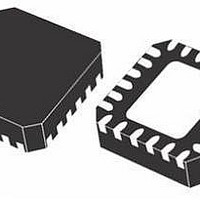
... VFQFPN-48 (7x7x1.0 mm) package mechanical data Dim ddd 44/47 mm Min. Typ. 0.80 0.90 0.02 0.65 0.25 0.18 0.23 6.85 7.00 2.25 4.70 6.85 7.00 2.25 4.70 0.45 0.50 0.30 0.40 Doc ID 13510 Rev 3 PM6641 Max. 1.00 0.05 1.00 0.30 7.15 5.25 7.15 5.25 0.55 0.50 0.08 ...
Page 45
... PM6641 Figure 36. VFQFPN-48 (7x7x1.0 mm) package drawings Doc ID 13510 Rev 3 Package mechanical data 45/47 ...
Page 46
... Document status promoted from preliminary data to datasheet. Updated: Table 2 on page 2 Chapter 7: Device description on page Added: Chapter 9: Application examples on page Layout guidelines on page 40 3 Updated Table 4 on page 8 Doc ID 13510 Rev 3 Changes 6, Table 3 on page 8, Table 6 on page 19, 41., Chapter 8.5: PM6641 10, ...
Page 47
... PM6641 Information in this document is provided solely in connection with ST products. STMicroelectronics NV and its subsidiaries (“ST”) reserve the right to make changes, corrections, modifications or improvements, to this document, and the products and services described herein at any time, without notice. All ST products are sold pursuant to ST’s terms and conditions of sale. ...