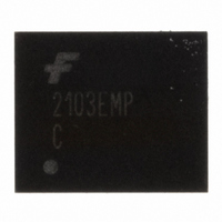
FAN2103EMPX Fairchild Semiconductor, FAN2103EMPX Datasheet - Page 10

FAN2103EMPX
Manufacturer Part Number
FAN2103EMPX
Description
IC BUCK SYNC ADJ 3A 25MLP
Manufacturer
Fairchild Semiconductor
Series
TinyBuck™r
Type
Step-Down (Buck)r
Datasheet
1.FAN2103EMPX.pdf
(14 pages)
Specifications of FAN2103EMPX
Internal Switch(s)
Yes
Synchronous Rectifier
Yes
Number Of Outputs
1
Voltage - Output
3 ~ 21 V
Current - Output
3A
Frequency - Switching
200kHz ~ 600kHz
Voltage - Input
3 ~ 24 V
Operating Temperature
-40°C ~ 85°C
Mounting Type
Surface Mount
Package / Case
25-MLP
Power - Output
2.8W
Mounting Style
SMD/SMT
Efficiency
95 %
Input / Supply Voltage (max)
24 V
Input / Supply Voltage (min)
3 V
Maximum Operating Temperature
+ 85 C
Minimum Operating Temperature
- 40 C
Operating Temperature Range
- 40 C to + 85 C
Output Current
3 A
Output Power
2.8 W
Output Voltage
3.2 V
Supply Current
8 mA
Switching Frequency
600 KHz
For Use With
FEB207 - BOARD EVAL FOR FAN2103
Lead Free Status / RoHS Status
Lead free / RoHS Compliant
Other names
FAN2103EMPXTR
© 2007 Fairchild Semiconductor Corporation
FAN2103 • Rev. 1.0.6
Circuit Description
Initialization
Once V
HIGH, the IC checks for an open or shorted FB pin
before releasing the internal soft-start ramp (SS).
If R1 is open (as shown in Figure 1), the error amplifier
output (COMP) is forced LOW and no pulses are
generated. After the SS ramp times out (T1.0), an under-
voltage latched fault occurs.
If the parallel combination of R1 and R
internal SS ramp is not released and the regulator does
not start.
Soft-Start
Once internal SS ramp has charged to 0.8V (T0.8), the
output voltage is in regulation. Until SS ramp reaches
1.0V (T1.0), the “Fault Latch” is inhibited.
To avoid skipping the soft-start cycle, it is necessary to
apply V
Soft-start time is a function of oscillator frequency.
The regulator does not allow the low-side MOSFET to
operate in full synchronous rectification mode until
internal SS ramp reaches 95% of V
helps the regulator start against pre-biased outputs (as
shown in Figure 16) and ensures that inductor current
does not "ratchet" up during the soft-start cycle.
V
resets the IC.
CC
UVLO or toggling the EN pin discharges the SS and
IN
CC
Figure 21. Soft-Start Timing Diagram
before V
EN
FB
SS
exceeds the UVLO threshold and EN is
CC
1.35V
reaches its UVLO threshold.
3200 CLKs
4000 CLKs
2400 CLKs
1.0V
0.8V
T0.8
T1.0
REF
BIAS
Fault
Latch
Enable
0.8V
(~0.76V). This
is ≤ 1KΩ, the
10
Bias Supply
The FAN2103 requires a 5V supply rail to bias the IC
and provide gate-drive energy and controller power.
Connect a ≥ 1.0µf X5R or X7R decoupling capacitor
between VCC and PGND. Whenever the EN pin is
pulled up to V
be turned ON after V
turned ON using EN pin with an external control after
V
sequencing is not relevant.
Since V
supply current is frequency and voltage dependent.
Approximate V
where frequency (f) is expressed in KHz.
Setting the Output Voltage
The output voltage of the regulator can be set from 0.8V
to ~80% of V
R
The internal reference is 0.8V with 650nA, sourced from
the FB pin to ensure that if the pin is open, the regulator
does not start.
The external resistor divider is calculated using:
Connect R
Setting the Frequency
Oscillator frequency is determined by an external resistor,
R
where R
where frequency (f) is expressed in KHz.
The regulator does not start if R
I
R
R
f
CC
0
(
CC
T,
BIAS
KHz
T
BIAS
8 .
connected between the R(T) pin and AGND:
K (
(
mA
V
Ω
)
and V
in Figure 1).
=
)
=
)
CC
T
=
(
=
V
65
is expressed in KΩ.
(
OUT
BIAS
is used to drive the internal MOSFET gates,
. 4
10
IN
58
•
CC
IN
6
R
R
10
between FB and AGND.
CC
−
/
1
, the 5V supply connected to V
+
T
65
come up, the V
by an external resistor divider (R1 and
) f
0
6
current (I
)
[(
8 .
+
−
V
V
135
135
CC
IN
227
+
comes up. If the power supply is
650
−
5
CC
nA
+
) can be calculated using:
. 0
013
T
is left open.
CC
)
•
f (
and V
−
128
www.fairchildsemi.com
)]
CC
IN
should
power
(1)
(2)
(3)
(4)


