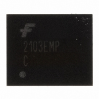
FAN2103EMPX Fairchild Semiconductor, FAN2103EMPX Datasheet - Page 3

FAN2103EMPX
Manufacturer Part Number
FAN2103EMPX
Description
IC BUCK SYNC ADJ 3A 25MLP
Manufacturer
Fairchild Semiconductor
Series
TinyBuck™r
Type
Step-Down (Buck)r
Datasheet
1.FAN2103EMPX.pdf
(14 pages)
Specifications of FAN2103EMPX
Internal Switch(s)
Yes
Synchronous Rectifier
Yes
Number Of Outputs
1
Voltage - Output
3 ~ 21 V
Current - Output
3A
Frequency - Switching
200kHz ~ 600kHz
Voltage - Input
3 ~ 24 V
Operating Temperature
-40°C ~ 85°C
Mounting Type
Surface Mount
Package / Case
25-MLP
Power - Output
2.8W
Mounting Style
SMD/SMT
Efficiency
95 %
Input / Supply Voltage (max)
24 V
Input / Supply Voltage (min)
3 V
Maximum Operating Temperature
+ 85 C
Minimum Operating Temperature
- 40 C
Operating Temperature Range
- 40 C to + 85 C
Output Current
3 A
Output Power
2.8 W
Output Voltage
3.2 V
Supply Current
8 mA
Switching Frequency
600 KHz
For Use With
FEB207 - BOARD EVAL FOR FAN2103
Lead Free Status / RoHS Status
Lead free / RoHS Compliant
Other names
FAN2103EMPXTR
© 2007 Fairchild Semiconductor Corporation
FAN2103 • Rev. 1.0.6
Pin Configuration
Pin Definitions
P3, 21-23
P1, 6-12
P2, 2-5
Pin
13
14
15
16
17
18
19
20
24
25
1
PGOOD
Name
COMP
PGND
AGND
RAMP
BOOT
VCC
R(T)
ILIM
SW
VIN
EN
NC
FB
Description
Switching Node.
Power Input Voltage. Connect to the main input power source.
Power Ground. Power return and Q2 source.
High-side Drive BOOT Voltage. Connect through capacitor (C
an internal synchronous bootstrap diode to recharge the capacitor on this pin to V
SW is LOW.
Power-Good Flag. An open-drain output that pulls LOW when FB is outside a ±10% range
of the reference when EN is HIGH. PGOOD does not assert HIGH until the fault latch is
enabled.
ENABLE. Enables operation when pulled to logic HIGH or left open. Toggling EN resets the
regulator after a latched fault condition. This input has an internal pull-up when the IC is
functioning normally. When a latched fault occurs, EN is discharged by a current sink.
Input Bias Supply for IC. The IC’s logic and analog circuitry are powered from this pin.
Analog Ground. The signal ground for the IC. All internal control voltages are referred to
this pin. Tie this pin to the ground island/plane through the lowest impedance connection.
Current Limit. A resistor (R
limit trip threshold lower than the default setting.
Oscillator Frequency. A resistor (R
frequency.
Output Voltage Feedback. Connect through a resistor divider to the output voltage.
Compensation. Error amplifier output. Connect the external compensation network
between this pin and FB.
No Connect. This pin is not used.
Ramp Amplitude. A resistor (R
amplitude and provides voltage feedforward functionality.
Figure 3. MLP 5x6mm Pin Configuration (Bottom View)
ILIM
) from this pin to AGND can be used to program the current-
RAMP
3
) connected from this pin to VIN sets the ramp
T
) from this pin to AGND sets the PWM switching
BOOT
) to SW. The IC includes
www.fairchildsemi.com
CC
when


