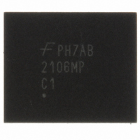
FAN2106MPX Fairchild Semiconductor, FAN2106MPX Datasheet - Page 4

FAN2106MPX
Manufacturer Part Number
FAN2106MPX
Description
IC BUCK SYNC ADJ 6A 25MLP
Manufacturer
Fairchild Semiconductor
Series
TinyBuck™r
Type
Step-Down (Buck)r
Datasheet
1.FAN2106MPX.pdf
(15 pages)
Specifications of FAN2106MPX
Internal Switch(s)
Yes
Synchronous Rectifier
Yes
Number Of Outputs
1
Voltage - Output
3 ~ 21 V
Current - Output
6A
Frequency - Switching
300kHz ~ 600kHz
Voltage - Input
3 ~ 24 V
Operating Temperature
-10°C ~ 85°C
Mounting Type
Surface Mount
Package / Case
25-MLP
Power - Output
2.8W
Mounting Style
SMD/SMT
Operating Temperature Range
- 10 C to + 85 C
Output Voltage
0.4 V to 3.2 V
Primary Input Voltage
24V
No. Of Outputs
1
Output Current
6A
No. Of Pins
25
Filter Terminals
SMD
Output Current Max
6A
Rohs Compliant
Yes
Input Voltage Primary Max
24V
For Use With
FEB167 - BOARD EVAL FOR FAN2106
Lead Free Status / RoHS Status
Lead free / RoHS Compliant
Other names
FAN2106MPXTR
Available stocks
Company
Part Number
Manufacturer
Quantity
Price
Part Number:
FAN2106MPX
Manufacturer:
FAIRCHILD/仙童
Quantity:
20 000
© 2009 Fairchild Semiconductor Corporation
FAN2106 • Rev. 1.1.0
Recommended Operating Conditions
The Recommended Operating Conditions table defines the conditions for actual device operation. Recommended
operating conditions are specified to ensure optimal performance to the datasheet specifications. Fairchild does not
recommend exceeding them or designing to absolute maximum ratings.
Thermal Information
Absolute Maximum Ratings
Stresses exceeding the absolute maximum ratings may damage the device. The device may not function or be
operable above the recommended operating conditions and stressing the parts to these levels is not recommended.
In addition, extended exposure to stresses above the recommended operating conditions may affect device
reliability. The absolute maximum ratings are stress ratings only.
Note:
1.
Symbol
Symbol
BOOT to PGND
θ
VCC to AGND
T
VIN to PGND
BOOT to SW
SW to PGND
All other pins
V
f
θ
J-PCB
Parameter
V
P
Typical thermal resistance when mounted on a four-layer, two-ounce PCB, as shown in Figure 26. Actual results
are dependent on mounting method and surface related to the design.
T
T
T
SW
STG
JC
CC
IN
A
L
D
J
ESD
Storage Temperature
Lead Soldering Temperature, 10 Seconds
Thermal Resistance: Junction-to-Case
Thermal Resistance: Junction-to-Mounting Surface
Power Dissipation, T
Bias Voltage
Supply Voltage
Ambient Temperature
Junction Temperature
Switching Frequency
AGND = PGND
Continuous
Transient (t < 20ns, f < 600KHz)
Human Body Model, JEDEC JESD22-A114
Charged Device Model, JEDEC JESD22-C101
Parameter
A
= 25°C
Parameter
Conditions
VCC to AGND
VIN to PGND
FAN2106MPX
FAN2106EMPX
Conditions
4
P1 (Q2)
P2 (Q1)
P3
Min.
Min.
200
-10
-40
4.5
-65
3
Min.
-0.3
-0.5
-5.0
-0.3
2.0
2.5
Typ.
Typ.
35
5.0
4
7
4
(1)
V
Max.
CC
24.0
30.0
6.0
28
35
6
+0.3
Max.
Max.
+125
+150
+300
2.8
+85
+85
600
5.5
24
(1)
www.fairchildsemi.com
Unit
kV
°C/W
°C/W
V
V
V
V
V
V
Unit
Unit
KHz
°C
°C
°C
°C
W
V
V


