LM22678TJE-5.0/NOPB National Semiconductor, LM22678TJE-5.0/NOPB Datasheet - Page 7
LM22678TJE-5.0/NOPB
Manufacturer Part Number
LM22678TJE-5.0/NOPB
Description
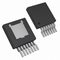
IC REG SWITCH BUCK 5A 5V TO263-7
Manufacturer
National Semiconductor
Series
SIMPLE SWITCHER®r
Type
Step-Down (Buck)r
Datasheet
1.LM22678TJE-ADJNOPB.pdf
(16 pages)
Specifications of LM22678TJE-5.0/NOPB
Internal Switch(s)
Yes
Synchronous Rectifier
No
Number Of Outputs
1
Voltage - Output
5V
Current - Output
5A
Frequency - Switching
500kHz
Voltage - Input
4.5 ~ 42 V
Operating Temperature
-40°C ~ 125°C
Mounting Type
Surface Mount
Package / Case
TO-263-7 Thin
Primary Input Voltage
12V
No. Of Outputs
1
Output Voltage
5V
Output Current
5A
No. Of Pins
7
Operating Temperature Range
-40°C To +125°C
Msl
MSL 1 - Unlimited
Filter Terminals
SMD
Rohs Compliant
Yes
For Use With
551600233-001 - WEBENCH BUILD IT LM2267X TO-263
Lead Free Status / RoHS Status
Lead free / RoHS Compliant
Power - Output
-
Other names
LM22678TJE-5.0TR


Detailed Operating Description
The LM22678 switching regulator features all of the functions
necessary to implement an efficient high voltage buck regu-
lator using a minimum of external components. This easy to
use regulator integrates a 42V N-Channel switch with an out-
put current capability of 5A. The regulator control method is
based on voltage mode control with input voltage feed for-
ward. The loop compensation is integrated into the LM22678
so that no external compensation components need to be se-
lected or utilized. Voltage mode control offers short minimum
on-times allowing short duty-cycles necessary in high input
voltage applications. The operating frequency is fixed at
500kHz to allow for small external components while avoiding
excessive switching losses. The output voltage can be set as
low as 1.285V with the -ADJ device. Fault protection features
include current limiting, thermal shutdown and remote shut-
down capability. The device is available in the TO-263 THIN
package featuring an exposed pad to aid thermal dissipation.
The functional block diagram with typical application of the
LM22678 are shown in
The internal compensation of the -ADJ option of the LM22678
is optimized for output voltages up to 5V. If an output voltage
of 5V or higher is needed, the -5.0 fixed output voltage option
with an additional external resistive feedback voltage divider
may also be used.
Precision Enable
The precision enable pin (EN) can be used to shut down the
power supply. Connecting this pin to ground or to a voltage
less than typical 1.6V will completely turn off the regulator.
The current drain from the input supply when off is typically
25 µA with 12V input voltage. The power consumed during
this off state is mostly defined by an internal 2 MΩ resistor to
VIN. The enable pin has an internal pull-up current source of
approximately 6 µA. When driving the enable pin, the high
voltage level for the on condition should not exceed the 6V
absolute maximum limit. When enable control is not required,
the EN pin should be left floating. The precision feature en-
ables simple sequencing of multiple power supplies with a
resistor divider from another power supply.
The EN pin can also be used as an external UVLO to disable
the part when input voltage falls below a lower boundary of
operation. This is often used to prevent excessive battery dis-
charge. It can also be used to prevent early turn-on as Vin is
rising which can cause undesirable on-off toggling if Vin
droops below 4.5V during startup. Using EN as en external
UVLO is also recommended to prevent abnormal device op-
eration in applications where the input voltage falls below the
minimum operating voltage of 4.5V, during power down for
example.
Maximum Duty-Cycle / Dropout
Voltage
The typical maximum duty-cycle is 90% at 500 kHz switching
frequency. This corresponds to a typical minimum off-time of
200 ns. This forced off-time is important to provide enough
time for the Cboot capacitor to charge during each cycle.
The lowest input voltage required to maintain operation is:
Figure
1.
7
Where V
Schottky diode and V
power N-FET of the LM22678. The R
specified in the electrical characteristics section of this
datasheet to calculate V
the switching frequency.
Minimum Duty-Cycle
Besides a minimum off-time, there is also a minimum on-time
which will take effect when the output voltage is adjusted very
low and the input voltage is very high. Should the operation
require an on-time shorter than minimum, individual switching
pulses will be skipped.
Pulse skipping is a normal mode of operation which appears
as a decrease in switching frequency. It has no effect on op-
eration or regulation except for an increase in output ripple
voltage. The pulse skipping function is required to maintain
proper regulation and overcurrent protection under the full
range of operating conditions.
The specified typical minimum on time of 100 ns is based on
the blanking time during current limit operation. During normal
operation, the minimum on-time will also include the effect of
propagation delay. Assume approximately 150 ns as a typical
operating minimum on time.
where D is the duty-cycle.
Current Limit
When the power switch turns on, the slight capacitance load-
ing of the Schottky diode, D1, causes a leading-edge current
spike with an extended ringing period. This spike can cause
the current limit comparator to trip prematurely. A leading
edge blanking time (T
sampling the spike.
When the switch current reaches the current limit threshold
the switch is immediately turned off. If T
minimum (100 ns typical) the switcher will hold the output
current flat at the set current limit value. But if T
decreases to the minimum T
frequency decreases to 1/5 the typical frequency. This effec-
tively causes the output current to fold back to a lower and
safe value. When the current limit condition is removed the
switching frequency is restored to nominal. This 5X frequency
fold back will result in a lower duty cycle pulse of the power
switch to minimize the overall fault condition power dissipa-
tion.
D
is the forward voltage drop across the re-circulating
Q
BLK
is the voltage drop across the internal
Q
) of 100 ns (typical) is used to avoid
according to the FET current. F is
ON
(100 ns typical) the switching
DS(ON)
ON
is larger than the
of the FET is
www.national.com
ON
is at or
Related parts for LM22678TJE-5.0/NOPB
Image
Part Number
Description
Manufacturer
Datasheet
Request
R

Part Number:
Description:
IC REG SWITCH BUC 5A ADJ TO263-7
Manufacturer:
National Semiconductor
Datasheet:

Part Number:
Description:
5a Simple Switcher , Step-down Voltage Regulator With Precision Enable
Manufacturer:
National Semiconductor Corporation
Datasheet:

Part Number:
Description:
National Semiconductor [8-Bit D/A Converter]
Manufacturer:
National Semiconductor
Datasheet:
Part Number:
Description:
National Semiconductor [Media Coprocessor]
Manufacturer:
National Semiconductor
Datasheet:
Part Number:
Description:
Digitally Controlled Tone and Volume Circuit with Stereo Audio Power Amplifier, Microphone Preamp Stage and National 3D Sound
Manufacturer:
National Semiconductor
Datasheet:
Part Number:
Description:
Digitally Controlled Tone and Volume Circuit with Stereo Audio Power Amplifier, Microphone Preamp Stage and National 3D Sound
Manufacturer:
National Semiconductor
Datasheet:
Part Number:
Description:
AC97 Rev 2 Codec with Sample Rate Conversion and National 3D Sound
Manufacturer:
National Semiconductor
Part Number:
Description:
Manufacturer:
National Semiconductor
Datasheet:
Part Number:
Description:
Manufacturer:
National Semiconductor
Datasheet:
Part Number:
Description:
General Purpose, Low Voltage, Low Power, Rail-to-Rail Output Operational Amplifiers
Manufacturer:
National Semiconductor
Datasheet:
Part Number:
Description:
8-bit 20 MSPS flash A/D converter.
Manufacturer:
National Semiconductor
Datasheet:
Part Number:
Description:
Low Noise Quad Operational Amplifier
Manufacturer:
National Semiconductor
Datasheet:
Part Number:
Description:
Quad Differential Line Receivers
Manufacturer:
National Semiconductor
Datasheet:
Part Number:
Description:
Quad High Speed Trapezoidal? Bus Transceiver
Manufacturer:
National Semiconductor
Datasheet: