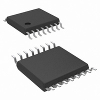
LM26400YMH/NOPB National Semiconductor, LM26400YMH/NOPB Datasheet

LM26400YMH/NOPB
Specifications of LM26400YMH/NOPB
LM26400YMH
Available stocks
Related parts for LM26400YMH/NOPB
LM26400YMH/NOPB Summary of contents
Page 1
... Additional features include programmable soft-start circuitry to reduce inrush current, pulse-by-pulse current limit and frequency foldback, integrated bootstrap structure and thermal shutdown. Typical Application © 2007 National Semiconductor Corporation Features ■ Input voltage range of 3-20V ■ Dual 2A output ■ ...
Page 2
Connection Diagrams 16-Lead ETSSOP (top view) NS Package Drawing MXA16A Ordering Information Order Number LM26400YMH LM26400YMHX LM26400YSD LM26400YSDX LM26400YSDE www.national.com 20200202 NSC Package Package Type Supplied As Drawing ETSSOP-16 MXA16A Rail of 92 Units ETSSOP-16 MXA16A 2500 Units on Tape ...
Page 3
Pin Descriptions Pin Name 1 FB1 2 SS1 3 EN1 4 AVIN 5 GND 6 EN2 7 SS2 8 FB2 9 BST2 10 SW2 11, 12, 13,14 PVIN 15 SW1 16 BST1 DAP Die Attach Pad Description Feedback pin of ...
Page 4
... Absolute Maximum Ratings If Military/Aerospace specified devices are required, please contact the National Semiconductor Sales Office/ Distributors for availability and specifications. AVIN, PVIN SWx Voltage BSTx Voltage BSTx to SW Voltage FBx Voltage ENx Voltage (Note 2) Electrical Characteristics Unless otherwise stated, the following conditions apply: AVIN = PVIN = V limits in boldface type apply over the junction temperature (T guaranteed through test, design, or statistical correlation ...
Page 5
Symbol Parameter Difference Between SS1 and ΔI SS SS2 Currents FB1 and FB2 Frequency Fold- V FB_F back Threshold Thermal Characteristics Symbol Description Junction-to-Ambient Thermal θ JA Resistance (Note 4) Junction-to-Case-Bottom θ JC Thermal Resistance Thermal Shutdown T SD Threshold ...
Page 6
Typical Performance Characteristics C for efficiency curves, loop gain plots and waveforms, and T Efficiency, V OUT Efficiency, V OUT AVIN Shutdown Current vs. Temperature www.national.com Unless otherwise specified or thermal-shutdown related 25°C for all others ...
Page 7
Switching Frequency vs. Temperature 20200207 Feedback Voltage vs 20200209 SS-Pin Current vs. Temperature 20200278 Feedback Voltage vs. Temperature Frequency Foldback FET R vs. Temperature DS_ON 7 20200208 20200210 20200221 www.national.com ...
Page 8
Switch Current Limit vs. Temperature Loop Gain, DCM Loop Gain, DCM www.national.com Loop Gain, CCM 20200234 Loop Gain, CCM 20200220 Load Step Response 20200222 8 20200219 20200236 20200223 ...
Page 9
Load Step Response 20200224 Start-Up (No Load) 20200228 Shutdown 20200229 Line Transient Response Start-Up (No Load) Thermal Shutdown 9 20200227 20200239 20200230 www.national.com ...
Page 10
Recovery from Thermal Shutdown Short-circuit Release www.national.com Short-circuit Triggering 20200240 20200232 10 20200231 ...
Page 11
Block Diagram 11 20200204 www.national.com ...
Page 12
Application Hints GENERAL The LM26400Y is a dual PWM peak-current mode buck reg- ulator with two integrated power MOSFET switches. The part is designed to be easy to use. The two regulators are mostly identical and share the same input ...
Page 13
See the section LOAD STEP RESPONSE for more details on C When one channel gets into over-current protection mode, the operation of the other channel will not be affected. LOOP STABILITY To the first ...
Page 14
This usually happens when the load toggles high at the time V just ramps down to its regulation level from an OUT overshoot. Figure 4 shows such a case where the load tog- gles between 1.7A and only 50mA. ...
Page 15
House keeping loss is: Finally the total power loss in the LM26400Y is: PROGRAMMING OUTPUT VOLTAGE First make sure the required maximum duty cycle in steady state is less than 80% so that the regulator will not lose reg- ulation. ...
Page 16
Choose a 5µ ferrite core inductor that has a saturation current around 3A at room temperature. For example, Sumida's CDRH6D26NP-5R0NC. If the maximum load current is significantly lower than 2A, pick an inductor with the same saturation rating ...
Page 17
R is the winding resistance of the inductor resistance of the MOSFET switch. Example 5V 3.3V 2A OUT1 OUT1 OUT2 = 30mΩ 170mΩ the same ...
Page 18
If a thermal couple has to be used, try to locate the hottest spot on the case-top first and then secure the thermal couple at exactly ...
Page 19
LM26400Y Design Examples Bill of Materials (Circuit 1, V Part Description Part Values C1 Capacitor, Ceramic 10µF, 16V, X5R C2 Capacitor, Ceramic 0.22µF, 16V, X5R C3 Capacitor, Ceramic 0.1µF, 6.3V, X5R C4 Capacitor, Ceramic 0.1µF, 6.3V, X5R C5 Capacitor, Ceramic ...
Page 20
LM26400Y Design Examples Bill of Materials (Circuit 1, V Part Description Part Values C1 Capacitor, Ceramic 10µF, 25V, X5R C2 Capacitor, Ceramic 0.22µF, 25V, X5R C3 Capacitor, Ceramic 0.1µF, 6.3V, X5R C4 Capacitor, Ceramic 0.1µF, 6.3V, X5R C5 Capacitor, Ceramic ...
Page 21
LM26400Y Design Examples Bill of Materials (Circuit 2, V Part Description Part Values C1 Capacitor, Ceramic 10µF, 6.3V, X5R C2 Capacitor, Ceramic 0.22µF, 6.3V, X5R C3 Capacitor, Ceramic 0.1µF, 6.3V, X5R C4 Capacitor, Ceramic 0.1µF, 6.3V, X5R C5 Capacitor, Ceramic ...
Page 22
Physical Dimensions www.national.com inches (millimeters) unless otherwise noted 16-Lead ETSSOP Package NS Package Number MXA16A 16-Lead LLP Package NS Package Number SDA16A 22 ...
Page 23
Notes 23 www.national.com ...
Page 24
... National Semiconductor and the National Semiconductor logo are registered trademarks of National Semiconductor Corporation. All other brand or product names may be trademarks or registered trademarks of their respective holders. ...


