LM2585T-ADJ/NOPB National Semiconductor, LM2585T-ADJ/NOPB Datasheet - Page 22
LM2585T-ADJ/NOPB
Manufacturer Part Number
LM2585T-ADJ/NOPB
Description
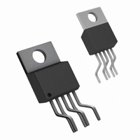
IC MULTI CONFIG ADJ 3A TO220-5
Manufacturer
National Semiconductor
Series
SIMPLE SWITCHER®r
Type
Step-Up (Boost), Flyback, Forward Converterr
Datasheet
1.LM2585T-ADJNOPB.pdf
(28 pages)
Specifications of LM2585T-ADJ/NOPB
Internal Switch(s)
Yes
Synchronous Rectifier
No
Number Of Outputs
1
Voltage - Output
Adjustable
Current - Output
3A
Frequency - Switching
100kHz
Voltage - Input
4 ~ 40 V
Operating Temperature
-40°C ~ 125°C
Mounting Type
Through Hole
Package / Case
TO-220-5 (Bent and Staggered Leads)
Package
5TO-220
Minimum Input Voltage
4 V
Maximum Input Voltage
40 V
Switching Frequency
85 to 115 KHz
Operating Supply Voltage
4 to 40 V
Maximum Output Current
3 A
Output Type
Adjustable
Output Voltage
11.52 to 12.48 V
Efficiency
93(Typ) %
Dc To Dc Converter Type
Step Up
Pin Count
5 +Tab
Input Voltage
40V
Switching Freq
85 TO 115KHz
Output Current
3A
Package Type
TO-220
Switching Regulator
Yes
Load Regulation
100mV
Line Regulation
100mV
Mounting
Through Hole
Input Voltage (min)
4V
Operating Temperature Classification
Automotive
Primary Input Voltage
40V
No. Of Outputs
1
No. Of Pins
5
Operating Temperature Range
-40°C To +125°C
Msl
MSL 1 - Unlimited
Filter Terminals
Through Hole
Rohs Compliant
Yes
For Use With
551011367-061 - BOARD WEBENCH LM2577,LM2585/87
Lead Free Status / RoHS Status
Lead free / RoHS Compliant
Power - Output
-
Lead Free Status / Rohs Status
Compliant
Other names
*LM2585T-ADJ
*LM2585T-ADJ/NOPB
LM2585T-ADJ
*LM2585T-ADJ/NOPB
LM2585T-ADJ


www.national.com
Application Hints
PROGRAMMING OUTPUT VOLTAGE
(SELECTING R
Referring to the adjustable regulator in
voltage is programmed by the resistors R
lowing formula:
Resistors R
can be compared with the 1.23V internal reference. With R
between 1k and 5k, R
For best temperature coefficient and stability with time, use
1% metal film resistors.
SHORT CIRCUIT CONDITION
Due to the inherent nature of boost regulators, when the out-
put is shorted (see
V
R
OUT
1
= R
= V
2
1
(V
and R
REF
OUT
1
AND R
(1 + R
/V
2
Figure
divide the output voltage down so that it
REF
1
is:
1
2
− 1)
/R
)
38), current flows directly from the
2
)
where V
where V
Figure
1
and R
REF
REF
38, the output
= 1.23V
= 1.23V
FIGURE 39. Flyback Regulator
FIGURE 38. Boost Regulator
2
by the fol-
2
22
input, through the inductor and the diode, to the output, by-
passing the switch. The current limit of the switch does not
limit the output current for the entire circuit. To protect the load
and prevent damage to the switch, the current must be ex-
ternally limited, either by the input supply or at the output with
an external current limit circuit. The external limit should be
set to the maximum switch current of the device, which is 3A.
In a flyback regulator application
dard transformers, the LM2585 will survive a short circuit to
the main output. When the output voltage drops to 80% of its
nominal value, the frequency will drop to 25 kHz. With a lower
frequency, off times are larger. With the longer off times, the
transformer can release all of its stored energy before the
switch turns back on. Hence, the switch turns on initially with
zero current at its collector. In this condition, the switch current
limit will limit the peak current, saving the device.
1251556
(Figure
1251555
39), using the stan-
Related parts for LM2585T-ADJ/NOPB
Image
Part Number
Description
Manufacturer
Datasheet
Request
R

Part Number:
Description:
IC MULTI CONFIG 12V 3A TO220-5
Manufacturer:
National Semiconductor
Datasheet:
Part Number:
Description:
IC MULTI CONFIG 5V 3A TO220-5
Manufacturer:
National Semiconductor
Datasheet:

Part Number:
Description:
DC/DC Converter IC
Manufacturer:
National Semiconductor
Datasheet:
Part Number:
Description:
IC MULTI CONFIG 3.3V 3A TO220-5
Manufacturer:
National Semiconductor
Datasheet:

Part Number:
Description:
SIMPLE SWITCHER 3A Flyback Regulator
Manufacturer:
National Semiconductor
Part Number:
Description:
National Semiconductor [8-Bit D/A Converter]
Manufacturer:
National Semiconductor
Datasheet:
Part Number:
Description:
National Semiconductor [Media Coprocessor]
Manufacturer:
National Semiconductor
Datasheet:
Part Number:
Description:
Digitally Controlled Tone and Volume Circuit with Stereo Audio Power Amplifier, Microphone Preamp Stage and National 3D Sound
Manufacturer:
National Semiconductor
Datasheet:
Part Number:
Description:
Digitally Controlled Tone and Volume Circuit with Stereo Audio Power Amplifier, Microphone Preamp Stage and National 3D Sound
Manufacturer:
National Semiconductor
Datasheet:
Part Number:
Description:
AC97 Rev 2 Codec with Sample Rate Conversion and National 3D Sound
Manufacturer:
National Semiconductor
Part Number:
Description:
Manufacturer:
National Semiconductor
Datasheet:
Part Number:
Description:
Manufacturer:
National Semiconductor
Datasheet: