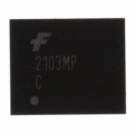
FAN2103MPX Fairchild Semiconductor, FAN2103MPX Datasheet

FAN2103MPX
Specifications of FAN2103MPX
Related parts for FAN2103MPX
FAN2103MPX Summary of contents
Page 1
... Battery-powered Equipment Set-top Boxes Point-of-load Regulation Servers Ordering Information Operating Part Number Temperature Range FAN2103MPX -10°C to 85°C FAN2103EMPX -40°C to 85°C For Fairchild’s definition of “green” please visit: http://www.fairchildsemi.com/company/green/rohs_green.html. © 2007 Fairchild Semiconductor Corporation FAN2103 • Rev. 1.0.6 Description The FAN2103 TinyBuck™ ...
Page 2
... Typical Application Diagram Block Diagram © 2007 Fairchild Semiconductor Corporation FAN2103 • Rev. 1.0.6 Figure 1. Typical Application Figure 2. Block Diagram 2 www.fairchildsemi.com ...
Page 3
... No Connect. This pin is not used. Ramp Amplitude. A resistor (R 25 RAMP amplitude and provides voltage feedforward functionality. © 2007 Fairchild Semiconductor Corporation FAN2103 • Rev. 1.0.6 BOOT ) from this pin to AGND can be used to program the current- ILIM ) from this pin to AGND sets the PWM switching ...
Page 4
... Power Dissipation Note: 1. Typical thermal resistance when mounted on a four-layer, two-ounce PCB, as shown in Figure 25. Actual results are dependent on mounting method and surface related to the design. © 2007 Fairchild Semiconductor Corporation FAN2103 • Rev. 1.0.6 Conditions Conditions VCC to AGND VIN to PGND FAN2103M ...
Page 5
... Over-Voltage Threshold Under-Voltage Shutdown Fault Discharge Threshold Fault Discharge Hysteresis Soft-Start V to Regulation (T0.8) OUT Fault Enable/SSOK (T1.0) Note: 2. Specifications guaranteed by design and characterization; not production tested. © 2007 Fairchild Semiconductor Corporation FAN2103 • Rev. 1.0.6 Conditions SW = Open 0.7V 5V 600KHz SW Shutdown ...
Page 6
... Recommended operating conditions are the result of using the circuit shown in Figure 1 unless otherwise noted. Parameter Control Functions EN Threshold, Rising EN Hysteresis EN Pull-up Resistance EN Discharge Current FB OK Drive Resistance PGOOD Threshold (Compared REF PGOOD Output Low © 2007 Fairchild Semiconductor Corporation FAN2103 • Rev. 1.0.6 (Continued) Conditions Auto-restart Mode FB < V REF FB > V REF I < 2mA OUT 6 Min ...
Page 7
... Figure 6. Frequency vs. R 1.60 1.40 1.20 1.00 Q2 ~0.35 %/ 0.80 0.60 -50 0 Temperature ( Figure 8. R vs. Temperature, Normalized © 2007 Fairchild Semiconductor Corporation FAN2103 • Rev. 1.0.6 1.20 1.10 1.00 0.90 0.80 50 100 150 - vs. Temperature, Figure 5. Reference Bias Current (I FB 1.02 1.01 1.00 ...
Page 8
... Efficiency Over V OUT Regulation Characteristic 1.828 1.826 1.824 1.822 Vo8V (V) 1.820 Vo12V (V) Vo18V (V) 1.818 0.00 0.50 1.00 1.50 Load Current (A) Figure 13. 1.8 V Regulation vs. Load OUT © 2007 Fairchild Semiconductor Corporation FAN2103 • Rev. 1.0.6 VCC P2 15 10K PGOOD 2.49K COMP 20 56p ILIM 17 ...
Page 9
... Typical operating characteristics using the circuit shown in Figure 10. V Figure 15. SW and V OUT Figure 17. Transient Response, 1.5-3A Load (Circuit Values Changed) Figure 19. Startup, 3A Load © 2007 Fairchild Semiconductor Corporation FAN2103 • Rev. 1.0.6 (Continued) Ripple, 3A Load Figure 16. Startup with 1V Pre-Bias =12V, V =5V, unless otherwise specified ...
Page 10
... V UVLO or toggling the EN pin discharges the SS and CC resets the IC. © 2007 Fairchild Semiconductor Corporation FAN2103 • Rev. 1.0.6 Bias Supply The FAN2103 requires a 5V supply rail to bias the IC and provide gate-drive energy and controller power. ...
Page 11
... EN restores operation after a CC normal soft-start cycle (refer to Auto-Restart section). The over-current protection fault latch is active during the soft-start cycle. Use a 1% resistor for R © 2007 Fairchild Semiconductor Corporation FAN2103 • Rev. 1.0 Loop Compensation The loop is compensated using a feedback network around the error amplifier ...
Page 12
... CC keep the 1µA current sink from discharging EN to 1.1V. Figure 24. Fault Latch with Delayed Auto-Restart © 2007 Fairchild Semiconductor Corporation FAN2103 • Rev. 1.0.6 Over-Temperature Protection FAN2103 incorporates an over-temperature protection circuit that sets the fault latch when a die temperature of about 160° ...
Page 13
... Package drawings are provided as a service to customers considering Fairchild components. Drawings may change in any manner without notice. Please note the revision and/or date on the drawing and contact a Fairchild Semiconductor representative to verify or obtain the most recent revision. Package specifications do not expand the terms of Fairchild’s worldwide terms and conditions, specifically the warranty therein, which covers Fairchild products. Always visit Fairchild Semiconductor’ ...
Page 14
... Fairchild Semiconductor Corporation FAN2103 • Rev. 1.0.6 14 www.fairchildsemi.com ...


