LM3673TL-ADJ/NOPB National Semiconductor, LM3673TL-ADJ/NOPB Datasheet
LM3673TL-ADJ/NOPB
Specifications of LM3673TL-ADJ/NOPB


Related parts for LM3673TL-ADJ/NOPB


LM3673TL-ADJ/NOPB Summary of contents
Page 1
... PB) versions. A high switch- ing frequency of 2 MHz (typ) allows the use of three tiny surface-mount components, an inductor and two ceramic ca- pacitors. Typical Application Circuits © 2006 National Semiconductor Corporation Features ■ 16 µA typical quiescent current ■ 350 mA maximum load capability ■ ...
Page 2
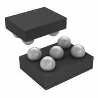
Connection Diagram and Package Mark Information FIGURE 3. 5-Bump MicroSMD Package NS Package Number TLA05CBA Pin Descriptions (5-Bump MicroSMD) Pin # Name GND www.national.com FIGURE 2. Typical Application Circuit for ...
Page 3
... Ordering Information (5-Bump MicroSMD) Voltage Option Order Number ADJ LM3673TL-ADJ LM3673TLX-ADJ LM3673TL-ADJ LM3673TLX-ADJ 1.2 LM3673TL-1.2 LM3673TLX-1.2 LM3673TL-1.2 LM3673TLX-1.2 1.5 LM3673TL-1.5 LM3673TLX-1.5 LM3673TL-1.5 LM3673TLX-1.5 1.8 LM3673TL-1.8 LM3673TLX-1.8 LM3673TL-1.8 LM3673TLX-1.8 1.875 LM3673TL-1.875 LM3673TLX-1.875 LM3673TL-1.875 LM3673TLX-1.875 Spec Package Marking NOPB NOPB NOPB NOPB NOPB NOPB ...
Page 4
... Continuous Power Dissipation (Note 3) Junction Temperature (T ) J-MAX Storage Temperature Range Maximum Lead Temperature (Soldering, 10 sec.) ESD Rating (Note 4) Electrical Characteristics apply over the full operating ambient temperature range (−30°C the LM3673TL with 3.6V IN Symbol Parameter V Input Voltage IN V Feedback Voltage (Fixed / ADJ ...
Page 5
Note 10: The input voltage range recommended for ideal applications performance for the specified output voltages are given below: ≤ 2.7V to 4.5V for 1.1V V < 1.5V IN OUT ≤ 2.7V to 5.5V for 1.5V ...
Page 6
Block Diagram www.national.com FIGURE 4. Simplified Functional Diagram 6 20183318 ...
Page 7
... Typical Performance Characteristics LM3673TL, Circuit of Figure 3.6V Quiescent Supply Current vs. Supply Voltage Feedback Bias Current vs. Temp R vs. Temperature DS(ON) = 1.5V 25°C, unless otherwise noted. OUT A Shutdown Current vs. Temp 20183304 Switching Frequency vs. Temperature 20183340 Open/Closed Loop Current Limit vs. Temperature 20183333 7 20183305 20183347 20183348 www ...
Page 8
Output Voltage vs. Supply Voltage (V = 1.5V) OUT Output Voltage vs. Output Current (V = 1.5V) OUT Efficiency vs. Output Current (V = 1.5V 2.2 µH, dcr = 200mΩ) OUT www.national.com Output Voltage vs. Temperature 20183329 Efficiency ...
Page 9
Efficiency vs. Output Current (V = 1.1V, L= 2.2 µH, dcr = 200mΩ) OUT-ADJ 20183341 Line Transient Response V = 1.5V (PWM Mode) OUT Load Transient Response (V = 1.5V) OUT (PFM Mode 0.5mA to 50mA) Efficiency vs. Output Current ...
Page 10
Mode Change by Load Transients V = 1.5V (PFM to PWM) OUT Start Up into PWM Mode V = 1.5V (Output Current= 150mA) OUT www.national.com Mode Change by Load Transients V = 1.5V (PWM to PFM) OUT 20183354 Start Up ...
Page 11
Operation Description DEVICE INFORMATION The LM3673, a high efficiency step down DC-DC switching buck converter, delivers a constant voltage from a single Li- Ion battery and input voltage ranging from 2.7V to 5.5V to portable devices such as cell phones ...
Page 12
FIGURE 6. Typical PFM Operation During PFM operation, the converter positions the output volt- age slightly higher than the nominal output voltage during PWM operation, allowing additional headroom for voltage drop during a load transient from light to heavy load. ...
Page 13
SHUTDOWN MODE Setting the EN input pin low (<0.4V) places the LM3673 in shutdown mode. During shutdown the PFET switch, NFET switch, reference, control and bias circuitry of the LM3673 are turned off. Setting EN high (>1.0V) enables normal operation. ...
Page 14
LM3673-ADJ Configurations For Various V V (V) R1(kΩ) OUT 1.1 240 1.2 280 1.3 320 1.5 357 1.6 442 1.7 432 1.8 464 1.875 523 2.5 402 2.8 464 3.3 562 INDUCTOR SELECTION There are two main considerations when choosing ...
Page 15
TABLE 1. Suggested Inductors and Their Suppliers Model BRL2518T2R2M DO3314-222MX LPO3310-222MX CDRH2D14-2R2 KSLI-2520101AG2R2 * LQM31PN2R2M00 LQM2HPN2R2MJ0 OUTPUT CAPACITOR SELECTION A ceramic output capacitor of 10 µF, 6.3V is sufficient for most applications. Use X7R or X5R types; do not use ...
Page 16
... MicroSMD PACKAGE ASSEMBLY AND USE Use of the microSMD package requires specialized board layout, precision mounting and careful re-flow techniques, as detailed in National Semiconductor Application Note 1112. Refer to the section "Surface Mount Technology (SMD) As- sembly Considerations". For best results in assembly, align- ment ordinals on the PC board should be used to facilitate placement of the device ...
Page 17
FIGURE 8. Top layer board layout for Micro SMD 17 20183349 www.national.com ...
Page 18
Physical Dimensions www.national.com inches (millimeters) unless otherwise noted 5-Bump (Large) MicroSMD Package, 0.5mm Pitch NS Package Number TLA05CBA The dimensions for X1, X2, and X3 are as given 1.057 mm +/- 0.030mm X2 = 1.387 mm +/- 0.030mm ...
Page 19
Notes 19 www.national.com ...
Page 20
... National Semiconductor and the National Semiconductor logo are registered trademarks of National Semiconductor Corporation. All other brand or product names may be trademarks or registered trademarks of their respective holders. ...