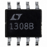
LT1308BCS8 Linear Technology, LT1308BCS8 Datasheet - Page 13

LT1308BCS8
Manufacturer Part Number
LT1308BCS8
Description
IC DC/DC CONV SINGLE CELL 8-SOIC
Manufacturer
Linear Technology
Type
Step-Up (Boost)r
Datasheet
1.LT1308ACS8PBF.pdf
(20 pages)
Specifications of LT1308BCS8
Internal Switch(s)
Yes
Synchronous Rectifier
No
Number Of Outputs
1
Voltage - Output
5V
Current - Output
1A
Frequency - Switching
600kHz
Voltage - Input
1 ~ 10 V
Operating Temperature
0°C ~ 70°C
Mounting Type
Surface Mount
Package / Case
8-SOIC (3.9mm Width)
Lead Free Status / RoHS Status
Contains lead / RoHS non-compliant
Power - Output
-
Available stocks
Company
Part Number
Manufacturer
Quantity
Price
Part Number:
LT1308BCS8
Manufacturer:
LINEAR/凌特
Quantity:
20 000
Part Number:
LT1308BCS8#PBF
Manufacturer:
LINEAR/凌特
Quantity:
20 000
Company:
Part Number:
LT1308BCS8#TR
Manufacturer:
LT
Quantity:
43
Part Number:
LT1308BCS8#TR
Manufacturer:
LT/凌特
Quantity:
20 000
Part Number:
LT1308BCS8#TRPBF
Manufacturer:
LINEAR/凌特
Quantity:
20 000
APPLICATIONS INFORMATION
COMPONENT SELECTION
Diodes
We have found ON Semiconductor MBRS130 and Inter-
national Rectifi er 10BQ015 to perform well. For applica-
tions where V
MBRS140 or 10BQ040.
Height limited applications may benefi t from the use of the
MBRM120. This component is only 1mm tall and offers
performance similar to the MBRS130.
Inductors
Suitable inductors for use with the LT1308A/LT1308B must
fulfi ll two requirements. First, the inductor must be able
to handle current of 2A steady-state, as well as support
transient and start-up current over 3A without inductance
decreasing by more than 50% to 60%. Second, the DCR
of the inductor should have low DCR, under 0.05Ω so
V
5V/DIV
V
OUT
OUT
10V/DIV
10V/DIV
1A/DIV
1A/DIV
V
Figure 17. Start-Up Waveforms of Figure 16’s Circuit
without Soft-Start Components
V
Figure 18. Start-Up Waveforms of Figure 16’s Circuit
with Soft-Start Components Added
SHDN
SHDN
12V
12V
I
I
5V
5V
L1
L1
OUT
exceeds 30V, use 40V diodes such as
5ms/DIV
50μs/DIV
1308 F18
1308 F17
that copper loss is minimized. Acceptable inductance
values range between 2μH and 20μH, with 4.7μH best for
most applications. Lower value inductors are physically
smaller than higher value inductors for the same current
capability.
Table 1 lists some inductors we have found to perform
well in LT1308A/LT1308B application circuits. This is not
an exclusive list.
Table 1
VENDOR
Murata
Sumida
Coiltronics
Coilcraft
Capacitors
Equivalent Series Resistance (ESR) is the main issue
regarding selection of capacitors, especially the output
capacitors.
The output capacitors specifi ed for use with the LT1308A/
LT1308B circuits have low ESR and are specifi cally
designed for power supply applications. Output voltage
ripple of a boost converter is equal to ESR multiplied by
switch current. The performance of the AVX TPSD227M006
220μF tantalum can be evaluated by referring to Figure 3.
When the load is 800mA, the peak switch current is approxi-
mately 2A. Output voltage ripple is about 60mV
ESR of the output capacitor is 60mV/2A or 0.03Ω. Ripple
can be further reduced by paralleling ceramic units.
Table 2 lists some capacitors we have found to perform
well in the LT1308A/LT1308B application circuits. This is
not an exclusive list.
Table 2
VENDOR
AVX
AVX
Taiyo Yuden
Taiyo Yuden
SERIES
X5R
X5R
TPS
TPS
LPO2506IB-472
CDRH734R7
LQH6C4R7
PART NO.
CTX5-1
TPSD227M006
TPSD107M010
LMK432BJ226
TMK432BJ106
LT1308A/LT1308B
PART NO.
VALUE
100μF, 10V
4.7μH
4.7μH
4.7μH
220μF, 6V
22μF, 10V
10μF, 25V
5μH
VALUE
770-436-1300
847-956-0666
561-241-7876
847-639-6400
803-448-9411
803-448-9411
408-573-4150
408-573-4150
PHONE NO.
PHONE NO.
P-P
13
, so the
1308abfb


