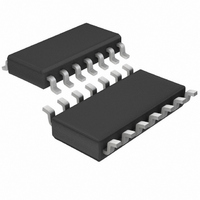
LTC1265CS Linear Technology, LTC1265CS Datasheet

LTC1265CS
Specifications of LTC1265CS
Available stocks
Related parts for LTC1265CS
LTC1265CS Summary of contents
Page 1
... The inductor current is user-programmable via an external current sense resistor. Operation up to 700kHz permits the use of small surface mount inductors and capacitors. , LTC and LT are registered trademarks of Linear Technology Corporation. Burst Mode is a trademark of Linear Technology Corporation. L1 ...
Page 2
... OUT C = 390pF 800mA (LTC1265C) T LOAD C = 390pF 800mA (LTC1265I) T LOAD ORDER PART NUMBER 14 SW LTC1265CS 13 PWR PGND LTC1265CS-5 11 SGND LTC1265CS-3.3 10 SHDN LTC1265IS 9 N SENSE = 110 C/W JA MIN TYP MAX UNITS 0.2 1 1.22 1.25 1.28 1.20 1.25 1.30 3.22 3.3 3.40 4 ...
Page 3
... I Shutdown Pin Input Current 10 Note 1: Absolute Maximum Ratings are those values beyond which the life of the device may be impaired. Note calculated from the ambient temperature T J dissipation P according to the following formulas: D LTC1265CS, LTC1265CS-3.3, LTC1265CS- • 110 C/ TYPICAL PERFOR A CE CHARACTERISTICS Efficiency vs Load Current ...
Page 4
LTC1265/LTC1265-3.3/LTC1265 TYPICAL PERFOR A CE CHARACTERISTICS DC Supply Current 2.1 DOES NOT INCLUDE GATE CHARGE 1.8 ACTIVE MODE 1.5 1.2 0.9 0.6 0.3 SLEEP MODE INPUT VOLTAGE (V) 1265 ...
Page 5
CTIO AL DIAGRA SLEEP + S – V TH2 V TH1 OPERATIO (Refer to Functional Diagram) The LTC1265 uses a constant off-time architecture to switch its internal P-channel power MOSFET. The off time ...
Page 6
LTC1265/LTC1265-3.3/LTC1265-5 U OPERATIO (Refer to Functional Diagram) capacitor discharges past V until its voltage drops TH1 below V . Comparator S then trips and a sleep signal is TH2 generated. The circuit now enters into sleep mode with the power ...
Page 7
U U APPLICATIO S I FOR ATIO Under short-circuit condition, the peak inductor current is determined by: = 150mV I (Amps) SC(PK) R SENSE In this condition, the LTC1265 automatically extends the off time of the P-channel MOSFET to allow ...
Page 8
LTC1265/LTC1265-3.3/LTC1265 APPLICATIO S I FOR ATIO P-channel switch duty cycle. At high input voltages, the diode conducts most of the time the diode conducts only a small fraction of the time. The most stressful condition for ...
Page 9
U U APPLICATIO S I FOR ATIO The output, Pin N-channel open drain that goes low when the battery voltage is below the threshold set by R3 and R4. In shutdown, the comparator is disabled and Pin ...
Page 10
LTC1265/LTC1265-3.3/LTC1265 APPLICATIONS INFORMATION output voltage can potentially float above the maximum allowable tolerance. To prevent this from occuring, a resistor must be connected between V with a value low enough to sink the maximum possible leakage current. THERMAL ...
Page 11
U U APPLICATIO S I FOR ATIO 1000pF 4 3900pF Figure 6. LTC1265 Layout Diagram (See Board Layout Checklist) Troubleshooting Hints Since efficiency is critical to LTC1265 applications very important to ...
Page 12
LTC1265/LTC1265-3.3/LTC1265 APPLICATIO S I FOR ATIO (a) POORLY DECOUPLED LTC1265 Design Example As a design example, assume 0.8A and f = 250kHz. With this information we can easily calculate all the important ...
Page 13
U TYPICAL APPLICATIO 270pF 3900pF 1k * AVX TPSD107K010 ** AVX TPSE227K010 † COILCRAFT D03316-473 †† DALE WSL2010-0.1-1% * AVX TPSD226K025 ** AVX TPSD107K010 † L1 SELECTION MANUFACTURER PART NO. COILCRAFT DO3316-473 COILTRONICS CTX50-4 LPT4545-500LA DALE ...
Page 14
LTC1265/LTC1265-3.3/LTC1265-5 U TYPICAL APPLICATIO S V (V) I (mA) IN OUT(MAX) 3.5V TO 7.5V 3.5 240 4.0 275 5.0 365 6.0 490 7.0 610 7.5 665 75pF L1A L1B 3 2 TOP VIEW 3300pF • L1A L1B SANYO ...
Page 15
... SENSE Information furnished by Linear Technology Corporation is believed to be accurate and reliable. However, no responsibility is assumed for its use. Linear Technology Corporation makes no represen- tation that the interconnection of its circuits as described herein will not infringe on existing patent rights. LTC1265/LTC1265-3.3/LTC1265-5 2.5mm Max Height 5V-to-3.3V (500mA) ...
Page 16
... TRICKLE CHARGE LTC1265 TA08 0.337 – 0.344* (8.560 – 8.738 0.150 – 0.157** (3.810 – 3.988 16V IN 20V 400mA, MS8 Q , MS8 IN to 500mA, 2.65V to 8.5V V OUT IN IN 126535fb LT/LCG 0800 2K REV B • PRINTED IN USA LINEAR TECHNOLOGY CORPORATION 1995 S14 1298 ...


