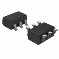
S-882155AMH-M3ETFG Seiko Instruments, S-882155AMH-M3ETFG Datasheet

S-882155AMH-M3ETFG
Specifications of S-882155AMH-M3ETFG
Available stocks
Related parts for S-882155AMH-M3ETFG
S-882155AMH-M3ETFG Summary of contents
Page 1
... Seiko Instruments Inc., 2002-2010 The S-8821 series is a CMOS step-up charge pump DC-DC converter with a voltage regulation function. The S-8821 series consists of an oscillation circuit, a controller, a reference voltage circuit, an error amplifier circuit, and an output switching transistor, and can regulate the output voltage by PFM control. ...
Page 2
... VOLTAGE REGULATION STEP-UP CHARGE PUMP DC-DC CONVERTER S-8821 Series Block Diagram VIN =4.7 μ SW1 SW2 C + =0.10 μ PUMP C − SW3 SW4 2 PFM control Switch oscillator control circuit circuit (1.0 MHz) Soft start circuit ON/OFF circuit ON/OFF Figure 1 Seiko Instruments Inc. ...
Page 3
... Product Name Structure • The output voltage and packages for the S-8821 Series can be selected at the user’s request. Refer to the “Product name” for the meanings of the characters in the product name, “Package” regarding the package drawings and “Product name list” for the full product names. ...
Page 4
... V 3.0 V 3.3 V 3.5 V 3.6 V 4.0 V 4.5 V 5.0 V 5.2 V 5.5 V Remark 1. Contact the SII sales department for products with an output voltage other than those specified above Please select products of environmental code = U for Sn 100%, halogen-free products. 4 Table 1 SOT-23-6W S-882125AMH-M2ATFz S-882130AMH-M2FTFz S-882133AMH-M2ITFz S-882135AMH-M2KTFz ...
Page 5
... C+ (positive pin) Charge-pump pump capacitor connection pin 3 C− (negative pin) Shutdown pin 4 ON/OFF High level (H) : normal operation (step-up) Low level (L) : step-up halt (all circuit halt) 5 GND GND pin 6 VOUT Voltage output pin Pin No. Symbol Charge-pump pump capacitor connection pin 1 ...
Page 6
... When mounted on board [Mounted board] (1) Board size: (2) Board name: JEDEC STANDARD51-7 Caution The absolute maximum ratings are rated values exceeding which the product could suffer physical damage. These values must therefore not be exceeded under any conditions. (1) When mounted on board 800 700 ...
Page 7
... In case of V ≤ 3 OUT IN * Actual output voltage OUT( Specified output voltage OUT(S) *3. The output current at which the output voltage becomes output current. *4. Design assurance *5. The ideal efficiency is indicated by the following expression. × I Efficiency (η)=(V OUT OUT *6. In case of V ≤ 2 ...
Page 8
... VOLTAGE REGULATION STEP-UP CHARGE PUMP DC-DC CONVERTER S-8821 Series Test Circuits 1. 4.7 μ 0.1 μF 4.7 μ VIN VOUT C+ GND C− ON/OFF A Figure 5 VIN VOUT C+ GND C− ON/OFF 10 μF A Figure 6 Seiko Instruments Inc. Rev.5.0 A _00 ...
Page 9
... Figure 7 shows the block diagram of the S-8821 Series. The S-8821 series controls the output voltage by using the pulse frequency modulation (PFM) method. The SW1 to SW4 switching transistors are switched ON/OFF with the clock generated by the internal oscillator circuit, and operates the step-up charge pump. ...
Page 10
... SW4 to ON (charge cycle). Following charging the electricity, in order to discharge the charged electricity to the output capacitance (C and SW4 to OFF (discharge cycle). The input voltage can be stepped constant voltage value by repeating this charge cycle and discharge cycle. Figure 8 shows the charge cycle, and Figure 9 shows the discharge cycle. ...
Page 11
... Shutdown Pin (ON/OFF Pin) Setting the ON/OFF pin to the Low level ("L") causes the voltage of the VOUT pin to change to the GND level and simultaneously the operation of all the internal circuit to stop. At this time, the consumption current is largely reduced level of approximately 0.3 μA. ...
Page 12
... Select a ceramic IN capacitor with a small equivalent series resistance (ESR). Although this figure varies according to the impedance of the power supply that is used as well as the load current value generally in the range of 4.7 μ μF. For the output capacitor (C voltage. A value of 10 μ ...
Page 13
... Moreover, in selecting C PUMP • The ON/OFF pin is configured as shown in Figure 9 and is neither pulled up or down internally not use this pin in a floating state. When not using the ON/OFF pin, connect it to the VIN pin. Moreover, please do not apply voltage higher than VIN + 0 ON/OFF pin. Current flows for a VIN pin through the protection diode inside IC. • ...
Page 14
... VOLTAGE REGULATION STEP-UP CHARGE PUMP DC-DC CONVERTER S-8821 Series Characteristics (Typical Data) (1) Output voltage vs. Operation input voltage S-882133A I OUT 3.50 3.45 3.40 3.35 3.30 3.25 3.20 3.15 3.10 1.5 2.0 2.5 3.0 3.5 V [V] IN (2) Output voltage vs. Output current S-882133A 3.50 3 ...
Page 15
... Operation input voltage S-882133A I OUT 100 1.5 2.0 2.5 3.0 3.5 V [V] IN *1. The ideal efficiency is indicated by the following expression. × I Efficiency (η)=(V OUT (6) Maximum oscillation frequency vs. Operation input voltage S-882133A 1300 1200 1100 1000 900 800 700 1.5 2.0 2.5 3.0 3 ...
Page 16
... VOLTAGE REGULATION STEP-UP CHARGE PUMP DC-DC CONVERTER S-8821 Series (7) Load fluctuation S-882133A CH1 10 mA CH2 ms/div.] CH1: V CH2: I (8) Input voltage fluctuation S-882133A CH1 3.3 V CH2 1 ms/div.] CH1: V CH2 S-882150A V =2 CH1 CH2 [20 mV/div.] OUT [2 mA/div.] OUT S-882150A I =10 mA OUT CH1 CH2 [20 mV/div ...
Page 17
...
Page 18
...
Page 19
...
Page 20
...
Page 21
...
Page 22
...
Page 23
...
Page 24
... Seiko Instruments Inc. is strictly prohibited. • The products described herein cannot be used as part of any device or equipment affecting the human body, such as exercise equipment, medical equipment, security systems, gas equipment, or any apparatus installed in airplanes and other vehicles, without prior written permission of Seiko Instruments Inc. ...


